| OCR Text |
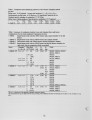
Show 4. Changes in the number N of fuel ports and of air ports enter through (14) and through the resulting change in the burner length scale d\2. The obvious effect is that of d\2 but, since J3\2 is also altered, the situation is complex. Furthermore, practically, changes in D\ and D2 are also likely to be made. 5. Increasing the combustion air temperature Ta from 400 °C to 600 °C without changing anything else, with y/\2 = 0.02 initially and (3\2 = 20°, lowers y/\2 to 0.0154 and shortens the flame by 9 %. 6. Effects of changes in the nature of the fuel, altering Wj, and in the excess air level, changing <pf, are predicted. 8.3.5. Compatibility of flame size and furnace size We noted above the powerful effect of of the fuel/air port separation angle J3\2 on flame size. Clearly, if J3\2 is too large, the C G R I burner flame confined in a furnace will impinge upon the furnace boundaries. Such effects can also be obtained by manipulation of the momentum flux ratio, ^12, but much less readily. Consider operation with y/\2 = 0.02, which is typical for the present work, and d\2 = 38.3 m m , 0\ = {30°, 35°, 42.5°, 65°}, 02. = 10°, the present values. The values of J3\2 calculated from (14), Table 8, range from 21.4° to 56.5° and closely approximate the difference 0\ - 02. The flow and flame dimensions estimated are: 1. The distance, xc, to confluence, from (8) 2. The flame length, as L/= 2xc. 3. The maximum excursion, ym, of the fuel jet trajectory from the burner axis, as estimated from (10) which is strictly valid for 02 = 0, as supposed in the development of the strong-jet/weak-jet model (Grandmaison, et al. 1996). 4. The maximum excursion, ym*, of the statistical outer boundary of the fuel jet, estimated as ym* =ym + 0.7xc(tan 02 + 0.194) = ym + 0.26xc, (20) where, as noted after (10), x » 0.7 xc aXy = ym. The factor tan 02 is an allowance for the fact that the air port axis is at an angle of 10° to the burner axis, not zero. The factor 0.194 allows for the lateral displacement of the fuel jet boundary from the trajectory (the distance between jet "edge" and "centreline"). When Lf> 3000 m m , the flame surely impinges upon the blind sidewall of our furnace (opposite the burner wall), and when jym* > 500 m m , the fuel jet (upstream of the main combustion zone) impinges upon the furnace roof and floor, in which case the flame is certainly awash over those surfaces. It should be kept in mind, from § 8.3.2, that actual flame lengths are at least 50 % greater than given by these predictions. It appears, then, that the flames at 0\ = 30° and 35° should fit comfortably into our furnace, with room to spare. The flame at 42.5° is pressed and almost certainly impinges with some intensity on roof, floor and blind sidewall. The flame at 65°, however, is potentially immensely greater than the furnace chamber. Clearly in this case the fuel jets head almost directly for the lateral furnace boundaries where they impinge, forming wall jets of complex structure. The meeting of fuel and air here is greatly complicated and the combustion zone involves a substantial portion of the furnace. 19 |