| OCR Text |
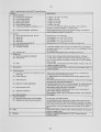
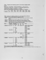
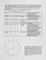
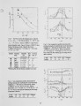
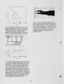
Show Table 7. Observations on flame appearance and combustion stability in the Series 3-XBM2-F three-burner trials. Burner parameters not varied: Dx = 6.35 m m , D2 = 19.05 m m , ft - 10°. The pilot burners were on throughout each trial. The abreviation ff means full-fire The combustion heat release rate at nominal "full fire" here was 1050 k W The temperatures Ta, Te and <7, r> are those observed at a particular time in each trial for which full energy balances were made. Trial 950316 950314 950324 950328 950323 950322 950320 950321 0i, deg 65 35 35 35 35 35 65 St, m 2 1 1 3 4 6 9 9 Ta @ff, °C 443 518 360 380 389 <550 Te @ff, °C 1347 1414 1055 1058 903 <220 <7> @ff, °C 1160 1135 966 940 835 Turndown limit, % of ff 58 @ 1.6 % 0 2 51 (S) 1.8 % 0 2 Not found 92 @ 1.6 % 0 2 , 46 @ 2.3 %, < 35 (S) 3.3 % 93@1.7%02, 67(5) 2.3 %02 Generally unstable Very unstable Remarks No luminosity about burner B1, slight to none at B3, light to heavy at B2, depending on turndown No luminosity , smooth combustion No luminosity, smooth combustion at full fire. Trial aborted without turndown tests, due to failure of two sink panels. No luminosity, smooth combustion Blue flames at Bl and B2, flame at B3 nearly invisible. Visible individual flames at Bl & B3. Flame at B2 shows intermittancy and surging, worsening with increasing temperature. Firing rate could not be raised much above low fire, due to heavy surging of furnace pressure, increasing with increasing furnace temperature. Trial terminated for reasons of safety Bluish darting flames not clearly linked to individual burners. Soft explosions and massive pressure fluctuations, worsening with rising furnace temperature. Trials terminated for reasons of safety. 1 ^ ® / / 2 7 /0 / / 1© \ \ \ 2© \ \ V ® 1 " 2 ..-©- cT 2 - 1 © \ \ ®2 r\, r2 ^ \ i 0 1 / / 02 / / / ® " 1 Fig. 1. Essential features of the C G R I burner, frontal view. Fuel ports, 1, alternate with air ports, 2, at uniform angular separation. There are N air ports and jVtuel ports. The fuel ports are of diameter D , at exit, and the air ports are of diameter D2. The fuel port axes make an angle 0, with the burner axis O, and the air port axes an angle ft. The centres-of-exit of the fuel ports are on a circle of radius r,, and those of the air ports are on a circle of radius r2. In the case illustrated, N = 6 and rx = r2. 33 |