| Title |
Demonstration of Combined NOx and SO2 Emission Control Technologies Involving Gas Reburning |
| Creator |
Folsom, Dr. Blair A.; Sommer, Todd M.; Payne, Dr. Roy |
| Publisher |
University of Utah |
| Date |
1991 |
| Spatial Coverage |
presented at Honolulu, Hawaii |
| Abstract |
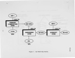
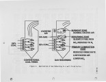
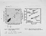
Three field evaluations of Gas Reburning (GR) integrated with other emission control technologies are in progress. Results from the first tests are presented. GR i s a combustion modification emission control technology. It can be easily retrofitted to virtually any combustion system. An appropriate amount of natural gas (typically 10-20 percent of the total heat input) is injected into the furnace above the main burners producing as lightly reducing zone. NOx is reduced by reaction with hydrocarbon fragments. Additiona1 overfire air is provided to burn out the remaining combustibles. GR alone can reduce NOx and SO2 emissions by 60 and 20 percent respectively. These control levels may be augmented by integrating GR with other synergistic control technologies. Integration with Sorbent Injection (GR-SI) can increase SO2 emission control to 50 percent. Integration with Low NOx Burners (GR-LNB) can increase NOx emission control to 75 percent. Two field evaluation projects involving GR-SI and GR-LNB are in progress at three sites. Initial NOx test results are available from a 71 MW tangentially fired boiler equipped with GR-SI. NOx emissions were reduced by about 70 percent in these short term tests exceeding the goal of 60 percent control. Additional long term tests will confirm these results in normal commercial operation. This work is part of the U.S. Department of Energy Clean Coal Technology Program. Cofunding is being provided by the Gas Research Institute, State of Illinois, Public Service Company of Colorado, Colorado Interstate Gas, Electric Power Research Institute, and Energy and Environmental Research Corporation. |
| Type |
Text |
| Format |
application/pdf |
| Language |
eng |
| Rights |
This material may be protected by copyright. Permission required for use in any form. For further information please contact the American Flame Research Committee. |
| Conversion Specifications |
Original scanned with Canon EOS-1Ds Mark II, 16.7 megapixel digital camera and saved as 400 ppi uncompressed TIFF, 16 bit depth. |
| Scanning Technician |
Cliodhna Davis |
| ARK |
ark:/87278/s6w95csf |
| Setname |
uu_afrc |
| ID |
7169 |
| Reference URL |
https://collections.lib.utah.edu/ark:/87278/s6w95csf |


