| OCR Text |
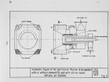
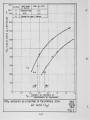
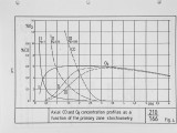
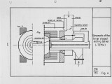
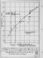
Show 10 - design; secondly, the expense of a completely new set of burners would have been financially unacceptable. The design chosen for the 70 MW staged mixing burner is shown schematically by Figure 6. The staging air nozzles were fitted on the burner circumference after removal of the webs and bending the tubes in four places of the membrane wall. Two flow control dampers were provided to allow the regulation of the staging air flow - branching off the secondary air supply - between minimum and maximum. The trimming dampers were fixed in their position when the power station was put into operation in October 1978. The staging air damper is connected to an automatic control system and can be readjusted at any time from the control room during operation. This allowes the burners also to be 6perated without staging air. During the commissioning tests the first step was to determine the influence of the staging air damper position on NO emissions and on the combustion behaviour. Simultaneously x 2 the tertiary and secondary air mass flows were measured. Figure 7 gives a summary of mumerous NO flue gas data at full load as a function of the stoichiometry of the primary zone, with the total air ratio as an additional parameter. Similar to the results achieved with the prototype burner (Figure 3) a strong reduction in NO flue gas emissions with decreasing primary zone air ratio was also achieved in the 7 00 MW power station with 24 full-size burners. On the basis of these results it can further be concluded that the total excess air has a negligible influence on NO emissions, additional in -TV Flame and flue gas measurements which were made during these ./. 9-10 |