| Title |
Advanced Steel Reheat Furnace |
| Creator |
Moyeda, D.; Sheldon, M.; Koppang, R.; Lanyi, M.; Li, X.; Eleazer, B. |
| Publisher |
University of Utah |
| Date |
1997 |
| Spatial Coverage |
presented at Chicago, Illinois |
| Abstract |
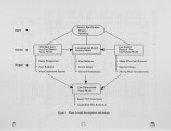
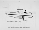
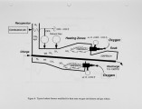
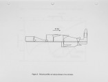
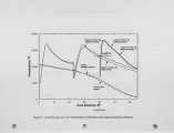
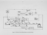
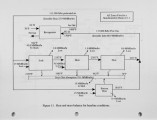
Energy and Environmental Research Corp. (EER) under a contract from the Department of Energy is pursuing the development and demonstration of an Advanced Steel Reheating Furnace. This paper reports the results of Phase I, Research, which has evaluated an advanced furnace concept incorporating two proven and commercialized technologies previously applied to other high temperature combustion applications: • EER's gas reburn technology (GR) for post combustion NOx control • Air Product's oxy-fuel enrichment air ( O E A) for improved flame heat transfer in the heating zones of the furnace. The combined technologies feature: • greater production throughput with associated furnace efficiency improvements • lowered N O x emissions • better control over the furnace atmosphere, whether oxidizing or reducing, leading to better control over surface finish |
| Type |
Text |
| Format |
application/pdf |
| Language |
eng |
| Rights |
This material may be protected by copyright. Permission required for use in any form. For further information please contact the American Flame Research Committee. |
| Conversion Specifications |
Original scanned with Canon EOS-1Ds Mark II, 16.7 megapixel digital camera and saved as 400 ppi uncompressed TIFF, 16 bit depth. |
| Scanning Technician |
Cliodhna Davis |
| ARK |
ark:/87278/s6tb19gs |
| Setname |
uu_afrc |
| ID |
14005 |
| Reference URL |
https://collections.lib.utah.edu/ark:/87278/s6tb19gs |


