| Title |
LIM Simulations of Gas Injection and Reburning in Two Coal-Fired Utility Boilers |
| Creator |
Frederiksen, Richard D.; Dahm, Werner J.A.; Pratapas, John; Serauskas, Robert V.; Bartok, William |
| Publisher |
University of Utah |
| Date |
1997 |
| Spatial Coverage |
presented at Chicago, Illinois |
| Abstract |
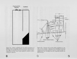
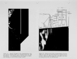
Results are presented from LIM-based simulations of fuel-lean gas reburning (FLGR) in two different types of coal-fired utility boilers to assess the capabilities of such simulations for supporting gas reburning system development. In the first of these boilers - a 112 MWe roof-fired pulverized coal unit (Duquesne Light Company's Elrama Unit 2 - the simulations were able to identify the origins of several unexpected factors that limited the NOx reduction attainable with the original reburn system design. The simulations also indicated specific changes in the gas injection system to achieve higher levels of NOx reduction at lower levels of gas input. In the second boiler - a 327 MWe cyclone fired unit (Commonwealth Edison's Joliet Unit 6 - the simulations were conducted in advance of any field data from the unit. Results correctly predicted all aspects of the reburn system performance subsequently measured under full load conditions without steam injection. These include quantitative predictions of the reduction in NOx emissions and increase in CO emissions. These results indicate that LIM-based simulations provide an effective way of obtaining accurate a priori assessment of the performance of gas reburning systems in a wide range of coal-fired utility boilers. |
| Type |
Text |
| Format |
application/pdf |
| Language |
eng |
| Rights |
This material may be protected by copyright. Permission required for use in any form. For further information please contact the American Flame Research Committee. |
| Conversion Specifications |
Original scanned with Canon EOS-1Ds Mark II, 16.7 megapixel digital camera and saved as 400 ppi uncompressed TIFF, 16 bit depth. |
| Scanning Technician |
Cliodhna Davis |
| ARK |
ark:/87278/s6h134mc |
| Setname |
uu_afrc |
| ID |
13772 |
| Reference URL |
https://collections.lib.utah.edu/ark:/87278/s6h134mc |


