| Title |
Development of Swirl Burner Series for Steel Making Processes |
| Creator |
Suzuki, Yutaka; Kaminaka, Motofumi; Kaburagi, Katuhiko; Yabuki, Kunihiro |
| Publisher |
University of Utah |
| Date |
1994 |
| Spatial Coverage |
presented at Maui, Hawaii |
| Abstract |
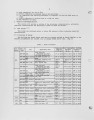
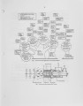
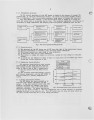
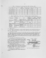
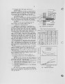
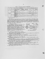
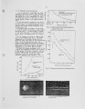
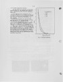
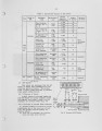
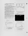
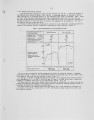
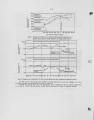
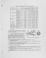
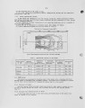
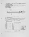
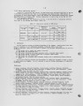
At Sumitomo Metals, we have developed several high efficiency burners using various fuels. The six main types are, 1) a SNT burner which produces a strong swirl flame, 2) a SSF burner which produces a bright stable flame when using pulverized coal, 3) a SSC burner producing a variable length flame with extremely low NOx emission, 4) a SCF burner producing a variable length curtain flame, 5) a SLG burner which produces a stable flame when using lean gases, and 6) a SNM burner which produces a reducing and direct heating flame in continuous he at treatment furnaces. The purpose of this paper is to present details on the structure and combustion characteristics of these burners and to outline their use in our factory. |
| Type |
Text |
| Format |
application/pdf |
| Language |
eng |
| Rights |
This material may be protected by copyright. Permission required for use in any form. For further information please contact the American Flame Research Committee. |
| Conversion Specifications |
Original scanned with Canon EOS-1Ds Mark II, 16.7 megapixel digital camera and saved as 400 ppi uncompressed TIFF, 16 bit depth. |
| Scanning Technician |
Cliodhna Davis |
| ARK |
ark:/87278/s6z89g05 |
| Setname |
uu_afrc |
| ID |
9982 |
| Reference URL |
https://collections.lib.utah.edu/ark:/87278/s6z89g05 |