| Title |
User Guide to the Burner Engineering Research Laboratory |
| Creator |
Fornaciari, Neal; Schefer, Robert; Paul, Phillip; Sanford, Robert; Claytor, Lloyd; Lubeck, Christi |
| Publisher |
University of Utah |
| Date |
1994 |
| Spatial Coverage |
presented at Maui, Hawaii |
| Abstract |
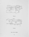
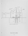
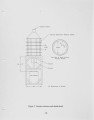
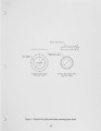
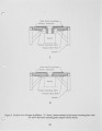
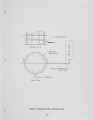
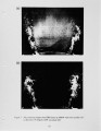
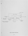
The Burner Engineering Research Laboratory (BERL) was established with the purpose of providing a facility where manufacturers and researchers can study industrial natural gas burners using conventional and laser-based diagnostics. To achieve this goal, an octagonal furnace enclosure with variable boundary conditions and optical access that can accommodate burners with firing rates up to 2.5 MMBtu per hour was built. In addition to conventional diagnostic capabilities like input/output measurements, exhaust gas monitoring, suction pyrometry and infurnace gas sampling, laser-based diagnostics available at BERL include planar Mie scattering, laser Doppler velocimetry and laser-induced fluorescence. This paper gives an overview of the operation of BERL and a description of the diagnostic capabilities and an estimate of the time required to complete each diagnostic for the potential user who is considering submitting a proposal. |
| Type |
Text |
| Format |
application/pdf |
| Language |
eng |
| Rights |
This material may be protected by copyright. Permission required for use in any form. For further information please contact the American Flame Research Committee. |
| Conversion Specifications |
Original scanned with Canon EOS-1Ds Mark II, 16.7 megapixel digital camera and saved as 400 ppi uncompressed TIFF, 16 bit depth. |
| Scanning Technician |
Cliodhna Davis |
| ARK |
ark:/87278/s6kp84r7 |
| Setname |
uu_afrc |
| ID |
7874 |
| Reference URL |
https://collections.lib.utah.edu/ark:/87278/s6kp84r7 |