| Title |
Development of a Generalized Burner Design Procedure |
| Creator |
Bortz, Steven J.; Yang, Shyh-Ching |
| Publisher |
University of Utah |
| Date |
1990 |
| Spatial Coverage |
presented at San Francisco, California |
| Abstract |
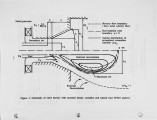
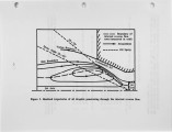
A generalized burner design procedure has been formulated using empirical and semi-empirical correlations for fuel burnout, ignition behavior and NOx emissions as a function of the burner inputs, burner geometry and swirl levels. The procedure has been used to design a dual fuel gas/oil low NOx burner which was consequently constructed and tested in the ERL combustion test facility. The measured burner performance was near the predicted performance for all the design values, with a 5/1 turndown and NOx emissions of less than 30 ppm on gas and 100 ppm on oil being achieved. |
| Type |
Text |
| Format |
application/pdf |
| Language |
eng |
| Rights |
This material may be protected by copyright. Permission required for use in any form. For further information please contact the American Flame Research Committee. |
| Conversion Specifications |
Original scanned with Canon EOS-1Ds Mark II, 16.7 megapixel digital camera and saved as 400 ppi uncompressed TIFF, 16 bit depth. |
| Scanning Technician |
Cliodhna Davis |
| ARK |
ark:/87278/s6zg6vtd |
| Setname |
uu_afrc |
| ID |
5823 |
| Reference URL |
https://collections.lib.utah.edu/ark:/87278/s6zg6vtd |


