| Title |
Experimental Evaluation of a High Efficiency Surface Combustor-Heater Concept With Low Pollutant Emissions |
| Creator |
Khinkis, Mark J.; Kunc, Walter; Xiong, Tian-yu |
| Publisher |
University of Utah |
| Date |
1989 |
| Spatial Coverage |
presented at Short Hills, New Jersey |
| Abstract |
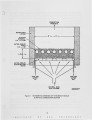
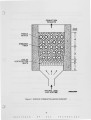
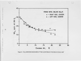
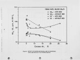
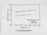
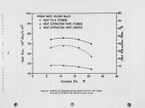
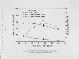
In a surface combustor-heater being developed by the Institute of Gas Technology (IGT), heat-exchange surfaces are embedded in a stationary bed (porous matrix) of refractory material where gaseous fuel is burned. The overall heat-transfer rate from the combustion products to the embedded heat-exchange surfaces can be significantly enhanced. Also, by removing heat simultaneously with the combustion process, NOx formation can be significantly reduced. To prove this concept, the bench-scale surface combustor-heater has been tested. Preliminary experimental results have demonstrated the remarkable advantages, such as high combustion intensity (up to 0.44 X 10^6 Btu/h-ft2) with just one row of tubes, high heat flux to the embedded tubes (up to 83 X 10^3 Btu/h-tt2), high heat-extraction rate (up to 60%), as well as low combustion emissions (NOx as low as 10 ppm and CO as low as 50 ppm, both at 0% O2). The surface combustor-heater performance data are rather promising. Further research and development work is recommended to explore the interaction between combustion and heat transfer and to develop data for optimizing the design and unit scale-up. |
| Type |
Text |
| Format |
application/pdf |
| Language |
eng |
| Rights |
This material may be protected by copyright. Permission required for use in any form. For further information please contact the American Flame Research Committee. |
| Conversion Specifications |
Original scanned with Canon EOS-1Ds Mark II, 16.7 megapixel digital camera and saved as 400 ppi uncompressed TIFF, 16 bit depth. |
| Scanning Technician |
Cliodhna Davis |
| ARK |
ark:/87278/s6vq357v |
| Setname |
uu_afrc |
| ID |
5655 |
| Reference URL |
https://collections.lib.utah.edu/ark:/87278/s6vq357v |