| Title |
Experimental Study of the Spray Flames in a Swirl-Stabilized Can Combustor |
| Creator |
Hsu, K. C.; Wu, G. Y.; Hwang, K. J.; Han, H. W.; Wang, M. R. |
| Publisher |
University of Utah |
| Date |
1989 |
| Spatial Coverage |
presented at Short Hills, New Jersey |
| Abstract |
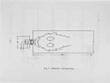
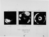
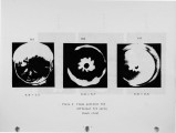
The aim of this experimental work is to study the effects of the swirling flow on the liquid-fueled spray flames. In this paper, the flame pattern and combustion flow species concentrations were measured using the direct photography and on-line gas analyzers respectively. The swirl numbers were changed from 0.3 to 1.2 by the axial vane type swirler. |
| Type |
Text |
| Format |
application/pdf |
| Language |
eng |
| Rights |
This material may be protected by copyright. Permission required for use in any form. For further information please contact the American Flame Research Committee. |
| Conversion Specifications |
Original scanned with Canon EOS-1Ds Mark II, 16.7 megapixel digital camera and saved as 400 ppi uncompressed TIFF, 16 bit depth. |
| Scanning Technician |
Cliodhna Davis |
| ARK |
ark:/87278/s6805556 |
| Setname |
uu_afrc |
| ID |
5587 |
| Reference URL |
https://collections.lib.utah.edu/ark:/87278/s6805556 |


