| Title |
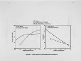
Additive Injection for NOx Control |
| Creator |
Mangal, R.; Mozes, M.; Gaikwad, R.; Thampi, R.; MacDonald, D. |
| Publisher |
University of Utah |
| Date |
1989 |
| Spatial Coverage |
presented at Short Hills, New Jersey |
| Abstract |
Injecting aqueous solutions of nitrogen-based additives into the furnace for reducing NOx emissions from coal-fired utility boilers has been studied at Ontario Hydro's 640 MJ/h Combustion Research Facility under conditions simulating full scale operation. Three additives were tested: urea, ammonia and ammonium carbonate. NOx reduction was found to be a function of injection temperature and mode of injection, additive stoichiometry, additive concentration and initial NOx concentration. Under optimized operating conditions while burning a 1.7% S eastern US bituminous coal and injecting urea cocurrently with the flue gas at a temperature of 1100°C, up to 90% NOx reduction can be achieved at an additive/NOx stoichiometry of 1.7. Under similar operating conditions, 84% removal was achieved with ammonia and 80% with ammonium carbonate. Ash resistivities and the performance of the electrostatic precipitator are not affected by in-furnace injection of these sorbents. |
| Type |
Text |
| Format |
application/pdf |
| Language |
eng |
| Rights |
This material may be protected by copyright. Permission required for use in any form. For further information please contact the American Flame Research Committee. |
| Conversion Specifications |
Original scanned with Canon EOS-1Ds Mark II, 16.7 megapixel digital camera and saved as 400 ppi uncompressed TIFF, 16 bit depth. |
| Scanning Technician |
Cliodhna Davis |
| ARK |
ark:/87278/s6jh3pqg |
| Setname |
uu_afrc |
| ID |
5359 |
| Reference URL |
https://collections.lib.utah.edu/ark:/87278/s6jh3pqg |


