| Title |
Development and Commercialization of an Efficient Cyclonic Incinerator for Wastes |
| Creator |
Crimmins, J.; Khinkis, M.; Kunc, V.; Korenberg, Dr. J.; Reider, C. |
| Publisher |
University of Utah |
| Date |
1987 |
| Spatial Coverage |
presented at Palm Springs, California |
| Abstract |
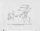
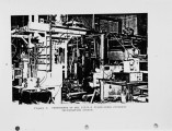
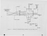
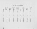
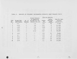
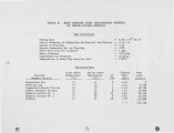
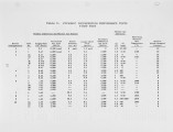
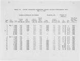
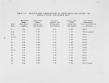
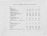
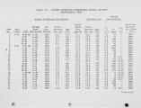
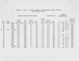
Cyclonic incinerators that operate with low excess air and high combustion intensity offer many advantages over commercially available incineration systems. The cyclonic incinerator allows incineration of liquid and gaseous wastes at minimal equipment and operating costs while simultaneously minimizing ashing/slagging problems inherent in conventional incinerators. A pilot-scale prototype cyclonic incineration system jointly developed by the Institute of Gas Technology (IGT) and York-Shipley, Inc. (Y-S) has demonstrated stable, highly efficient combustion of a liquid waste having a low (3200 Btu/lb) heating value. The unique design of the IGT/Y-S cyclonic incinerator features a compact combustion chamber, tangential or radial injection of atomized waste, tangential injection of a combustion air/natural gas mixture, and a water-cooled cyclonic chamber for slagging-mode operation. Unique operating characteristics of the incinerator include minimal auxiliary fuel (natural gas) consumption, enhanced dry-ash and molten slag separation from combustion products because of the centrifugal nature of the cyclonic swirl, and enhanced molten slag removal from the combustion chamber through a specially designed water-cooled refractory lining. Performance testing of the pilot-scale unit demonstrated stable combustion of 15 gal/h of a liquid waste containing 35 to 55 percent solids concentration. The heat contribution ratio of waste to natural gas averaged 60/40 (on a Btu basis). Major operating parameters during testing included a 0.8 x 10^6 Btu/h total firing rate, 2150°F combustion temperature, and specific heat release of 250,000 Btu/h per cubic foot of combustion volume. A 48-hour run demonstrated relatively small ash accumulation within the cyclonic chamber. A 60 gal/h cyclonic incineration demonstration system including heat recovery equipment, is being constructed for start-up in the spring of 1984. Commercial units of 300 gal/h are planned after intensive performance testing of the demonstration system. |
| Type |
Text |
| Format |
application/pdf |
| Language |
eng |
| Rights |
This material may be protected by copyright. Permission required for use in any form. For further information please contact the American Flame Research Committee. |
| Conversion Specifications |
Original scanned with Canon EOS-1Ds Mark II, 16.7 megapixel digital camera and saved as 400 ppi uncompressed TIFF, 16 bit depth. |
| Scanning Technician |
Cliodhna Davis |
| ARK |
ark:/87278/s6ft8pkr |
| Setname |
uu_afrc |
| ID |
4552 |
| Reference URL |
https://collections.lib.utah.edu/ark:/87278/s6ft8pkr |


