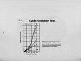
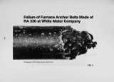
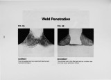
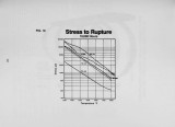
OCR Text |
Show in carburizing atmospheres. Butt welding is preferable to lap type of welding and wi II be discussed later. Heat resisting alloys are not free machining. They require sharp and heavy tools. Machinability rating is roughly 40% that of mild steel machine stock. Relatively low speeds with cuts deep enough to get under the skin are recommended. The rake of the tool should be such that it does not rub on the material which would work harden it, causing havoc with the tool life. Basic guidelines for design is to maintain minimum cross section, uniform cross section and allow for thermal expansion. Attempts should be made to eliminate fixed positions or rigidity. This is really not a reflection on the welding characteristics but a recognition of thermal expansion . An attempt at this is an articulated design which allows for freedom of metal movement. Often, applied stresses for a conveying system do not permit this, but when permissable it is quite effective. Uniform cross section is also an important consideration. Again, we relate to thermal gradients developed by differences of metal temperature. As indi cated previously, butt welding is the preferred method of joining because it maintains uniform cross section. I f a joi nt is lap welded, the cross section will generally be doubled. Due to the low thermal conductivity of heat resisting alloys, this can result in a significant difference of temperature between the cross section area. The importance of this is also illustrated by a typical cast alloy grid used in continuous pusher furnaces. The inner sections of the crossing member are cored. This results in a hole at each intersection which not only saves material but accomodates uniform cross section at each intersection. The above should not be considered intimi dating. The suggestions are not really due to the difficulties of fabricating the alloys, but rather a reflection of the way it is used. The harsher the service the more critical it is to develop good fabricating and welding techniques. APPLICAT IONS Fabricated radiant tubes are used extensively in thermal processing equipment with proven cost- effective service life. On occasion, a tube will fail prematurely, not related to the engineering properties of the metal. Illustrated is an example of a tube which obviously shows melting of the base metal (Figure 6). Records indicated that the operating temperature never got beyond 1850oF, which is probably true, and the past performance had been excellent. In this particular case , soot formation had accumulated on the surface of the tube, causing two problems . It became carburized , which can lower the melting point by perhaps 100°F. The burning of the soot d ue to oxidizing conditions p robably 282 resulted in an exothermic reaction raising the temperature above the melting point. It should be noted that any deposit on a container wi II prevent heat dissipation and wi II cause hot spots . The point here is that nickel chromium alloys do not melt at 1800° or 2000oF. If there is evidence of molten metal, the temperatu re at that point probably was in the vicinity of 2400oF. Outstanding performance has often been observed. Illustrated is a muffle used in a continuous hardening operation (Figure 7). The muffle has been removed for straightening and put back into service. The picture shows the condition of the muffle after 10 years, operating at 1550 to 161 OOF, two shifts per day, five days per week, idle at 1400oF, endothermic atmosphere. Admittedly, this is exceptional life, probably a record, but it does indicate the capability of a fabricated muffle, with the best combination of alloy and fabricating techniques compatible to the envi ronment. A NEW ALLOY A recent alloy development is the addition of small amounts of rare earths added during pouring of a heat to result in micro- alloying (MA) that greatly enhances the high temperatures properties of chromium- nickel austenitic alloys. RA 253MA is the first commercially available grade to use micro-alloy to extend the useful range of a lean nickel - chromium alloy base (21Cr- 11Ni - 1. 7Si - 0.04Ce). It has had extensive testing, including over 2.6 million hours of creep rupture testing through 20000F and has received ASME approval to 1650oF. The improvement in the oxidation is indicated in Figure 8. The yield strength and the tensile strength of RA 253MA do not drop off rapidly with increasing temperature. At room temperature the yield point is over 40% higher than T 309. At 15000F the yield strength is over 60% higher. It also has at least 4 times the creep strength of T 309 at 1600oF. Figure 9- 10 illustrate comparative creep and stress rupture data . A practical test illustrates the higher strength levels. Figure 11 shows 1 mm (.039") thick sheetmetal rings made of different materials. The rings were fastened to a steel plate and annealed in a car type fu rnace at 18300F (10000 C) . After 35 hours the rinQs of T321 and 310 were heavily deformed due to creep. The RA 253MA was fully intact with no measurably deformation equaling the creep strength of the N i alloy. |