| Title |
High Radiative Low NOx Flat Flame Oxy-Fuel Burner |
| Creator |
Fujisaki, Wataru; Nakamura, Tsuneaki |
| Publisher |
University of Utah |
| Date |
1998 |
| Spatial Coverage |
presented at Maui, Hawaii |
| Abstract |
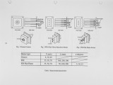
This paper describes the investigation on the characteristics of oxygen natural gas flames, to develop high performance oxy-fuel burners for glass melters. High radiative characteristics and low NOx emission are aimed at. The experiments first tested generic burners with an annular oxygen injector and a single-hole gas nozzle in the center. The flame showed higher radiative characteristics with relatively high luminosity and high NOx emission. The experiment then tested the FDI (fuel direct injection) burners equipped with one fuel gas nozzle in the center and two parallel oxygen nozzles at upper and lower positions of the fuel nozzle. The FDI technique, which was already utilized for low NOx emission for highly preheated air combustion, showed very low NOx emission with relatively low radiative characteristics. To obtain both high radiative characteristics with low NOx emission, an innovative FDI flat flame burner equipped with one fuel gas nozzle in the center and two inclined oxygen nozzles at upper and lower positions of the fuel nozzle was tested. A few degrees inclination of the oxygen nozzles created widely spread flat flame, resulting in substantial improvement of radiative heat while maintaining NOx emission remarkably low. The results of this study was finally led the FDI flat flame oxy-fuel burner that creates high radiative heat with low NOx emission. |
| Type |
Text |
| Format |
application/pdf |
| Language |
eng |
| Rights |
This material may be protected by copyright. Permission required for use in any form. For further information please contact the American Flame Research Committee. |
| Conversion Specifications |
Original scanned with Canon EOS-1Ds Mark II, 16.7 megapixel digital camera and saved as 400 ppi uncompressed TIFF, 16 bit depth. |
| Scanning Technician |
Cliodhna Davis |
| ARK |
ark:/87278/s6pr7zmm |
| Setname |
uu_afrc |
| ID |
13502 |
| Reference URL |
https://collections.lib.utah.edu/ark:/87278/s6pr7zmm |


