| Title |
Industrial Furnace Design Intelligent Support System |
| Creator |
Imanari, Takehito; Takei, Masaru; Nakamura, Tsuneaki; Osawa, Akira; Aoki, Syuichi |
| Publisher |
University of Utah |
| Date |
1998 |
| Spatial Coverage |
presented at Maui, Hawaii |
| Abstract |
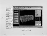
This paper describes the development and application of "if-Diss" (Industrial Furnace Design Intelligent Support System), a specialized CFD (Computational Fluid Dynamics) preprocessor for industrial furnaces. if-Diss is aimed to maximize the potential of CFD methods whose wider application has been expected to optimize design parameters as well as operating conditions of a wide variety of industrial furnaces. Having compiled a lot of know-how and expertise to model various furnaces, if-Diss facilitate the use of CFD, making it more attractive for furnace designers and engineers. if-Diss, developed by Tokyo Gas, in collaboration with Osaka Gas and Toho Gas, works as a front-end processor for major CFD solvers such as CFX, FLUENT/UNS and STAR-CD. if-Diss intelligently specifies numerical conditions suitable for industrial furnaces and generates input files to forward them to the CFD solvers. It consists of graphical user interface with a grid generator and a data-base of various analytical models. Analytical models, coded as user defined subprograms, allow users without detailed mathematical backgrounds to simulate complicated phenomena in the furnace. Coded in JAVA language, which runs under the internet browser, if-Diss can be used through network, thereby making it more user friendly and handy. |
| Type |
Text |
| Format |
application/pdf |
| Language |
eng |
| Rights |
This material may be protected by copyright. Permission required for use in any form. For further information please contact the American Flame Research Committee. |
| Conversion Specifications |
Original scanned with Canon EOS-1Ds Mark II, 16.7 megapixel digital camera and saved as 400 ppi uncompressed TIFF, 16 bit depth. |
| Scanning Technician |
Cliodhna Davis |
| ARK |
ark:/87278/s6tt4tk9 |
| Setname |
uu_afrc |
| ID |
12438 |
| Reference URL |
https://collections.lib.utah.edu/ark:/87278/s6tt4tk9 |


