| Title |
Analysis of Combustion System Using High Temperature CO and N2 Mixed Gas |
| Creator |
Nakagawa, Junichi |
| Publisher |
University of Utah |
| Date |
1998 |
| Spatial Coverage |
presented at Maui, Hawaii |
| Abstract |
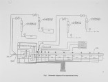
The experimental analysis and the numerical simulations for the combustion system using high temperature CO and N2 mixed gas are described. The purpose of this research is to understand the mechanism of combustion using high temperature CO and N2 mixed gas and to investigate the heat distribution by the combustion. The experiments using 600°C fuel gas mixed CO and N2, have been carried out, and the CO concentration profiles in the pipe were measured. These experiments were conducted in several CO concentrations in fuel gas, several oxygen concentrations in air and several diameters of nozzle. The results indicate that CO concentration profiles are mainly determined by the velocity of air jet from nozzle exit. Also numerical simulations incorporating an eddy-dissipation combustion model have a good agreement with experimental data It seems to be reasonable to conclude that the mechanism of this combustion is followed by turbulent diffusion. |
| Type |
Text |
| Format |
application/pdf |
| Language |
eng |
| Rights |
This material may be protected by copyright. Permission required for use in any form. For further information please contact the American Flame Research Committee. |
| Conversion Specifications |
Original scanned with Canon EOS-1Ds Mark II, 16.7 megapixel digital camera and saved as 400 ppi uncompressed TIFF, 16 bit depth. |
| Scanning Technician |
Cliodhna Davis |
| ARK |
ark:/87278/s6qc0643 |
| Setname |
uu_afrc |
| ID |
11398 |
| Reference URL |
https://collections.lib.utah.edu/ark:/87278/s6qc0643 |


