| Title |
NOx Reduction by Fuel Injection Recirculation: Insights from Laminar Flame Studies |
| Creator |
Feese, J. J.; Turns, S. R. |
| Publisher |
University of Utah |
| Date |
1996 |
| Spatial Coverage |
presented at Baltimore, Maryland |
| Abstract |
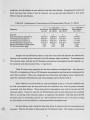
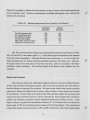
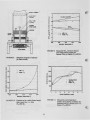
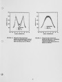
Flue-gas recirculation (FGR) is a well-known method used to control oxides of nitrogen (NOx) in industrial burner applications. Recent small- and large-scale experiments have shown that introducing the recirculated flue gases with the fuel results in a much greater reduction in NOx, per unit mass of gas recirculated, in comparison to introducing the flue gases with the combustion air. That fuel injection recirculation (FIR) is more effective than windbox FGR is quite remarkable. At present, however, there is no definitive understanding of why FIR is more effective than conventional FGR. The objective of the present investigation is to ascertain whether or not chemical and/or molecular transport effects alone can explain the differences in NOx reduction observed between FIR and FGR by studying laminar diffusion flames. Numerical simulations of counterflow diffusion flames using full kinetics were performed and NOx emission indices calculated for various conditions. Studies were conducted in which a N2 diluent was added either on the fuel- or air-side of the flame for conditions of either fixed initial velocities or fixed fuel mass flux. Results from these simulation studies indicate that a major factor in diluent effectiveness is the differential effect on flame zone residence times associated with fuel-side versus air-side dilution. Simulations in which flow velocities were fixed as diluent was added either to the air or fuel stream showed lower NOx emissions for air-side dilution; however, if instead, fuel mass fluxes were fixed as diluent was added, which results in an increase in the velocity of the streams, fuel-side dilution was more effective. Experiments using laminar jet flames were conducted in which either the air or fuel stream was diluted with N2. The experiments showed that fuel-side dilution results in somewhat greater NOx emission indices than air-side dilution. The higher flame temperatures measured with fuel dilution appear to be the principal cause of the higher emissions. Since fuel dilution is more effective than air dilution in suppressing in-flame soot formation, radiant heat losses with fuel dilution may be less causing temperatures to be somewhat higher. The results of both the numerical simulations and the experiments suggest that, although molecular transport and chemical kinetic phenomena are affected by the location of diluent addition depending on flow conditions, the greater effectiveness of FIR over FGR in practical applications more likely results from differences in turbulent mixing and heat transfer. |
| Type |
Text |
| Format |
application/pdf |
| Language |
eng |
| Rights |
This material may be protected by copyright. Permission required for use in any form. For further information please contact the American Flame Research Committee. |
| Conversion Specifications |
Original scanned with Canon EOS-1Ds Mark II, 16.7 megapixel digital camera and saved as 400 ppi uncompressed TIFF, 16 bit depth. |
| Scanning Technician |
Cliodhna Davis |
| ARK |
ark:/87278/s6qf8wgk |
| Setname |
uu_afrc |
| ID |
10894 |
| Reference URL |
https://collections.lib.utah.edu/ark:/87278/s6qf8wgk |