| OCR Text |
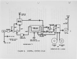
Show 3 and is fabricated in modules and assembled at manufacturing sites for shipment to the location of end use for quick installation and operation with little site preparation. The 200 kilowatt electrical umt comes on two skids which conform to shipping container and highway sizes. Because essentially no onsite construction is normally required, the umt can be operating within a week. The trial installation at a lumber mill in Georgia is being funded by the U.S. Environmental Protection Agency, the U.S. Department of Energy, the U.S. Department of Defense, and the Tennessee Valley Authority. DESCRIPTION OF FURNACE Figure 1 is a schematic representation of the fluid bed and radiant furnace. It contains all the elements relating to the combustion of biomass fuels for the power system. Also, it is important to keep in mind that though simple in concept, the conditions selected for the combustion process have evolved from numerous studies and experiments which have been directed toward maximizing the electrical power output from an externally fired gas turbine cycle, while at the same time emphasizing simplicity. As a generic type this combustor can be classified as a "bubbling" fluid bed operating at atmospheric to slightly subatmospheric pressure (negative draft furnace). Due to the fuel type currently being commercialized (wood) the distribution of air is one third to the fluid bed and two thirds to the secondary air. This is almost in proportion to the fixed carbon to volatiles in the fuel (24% and 72% respectively). Because of the large amount of secondary air, and the velocity of injection (200 - 300 ft/sec), the entire furnace can be modeled as a well stirred reactor. The mean residence time of the reactants in the furnace is approximately four seconds, and also would be the residence time calculated from the point of fuel injection. |