| Title |
Experimental Study of Ultra-Low Emission Radian Porous Burner |
| Creator |
Xiong, Tian-yu |
| Publisher |
University of Utah |
| Date |
1991 |
| Spatial Coverage |
presented at Hartford, Connecticut |
| Abstract |
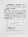
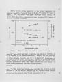
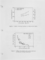
The objective of this study was to prove the concept of the novel gas-fired burner with stable internal porous-phase combustion. This novel combustion concept has good potential in increasing firing intensity and radiant heat output, and reducing combustion emissions for space and process heater applications. A bench-scale porous burner has been built and tested. The unique performances of the test burner, such as self-stabilization of combustion within the porous media in a large range of operating conditions, ultra-low NOx emissions from 1 to 12 vppm (at 0% O2), high radiant heat transfer rates up to 80 MBtu/h-ft2 (252 kW/m2) from the radiating surface, and high turndown ratio over 6:1 have been demonstrated. |
| Type |
Text |
| Format |
application/pdf |
| Language |
eng |
| Rights |
This material may be protected by copyright. Permission required for use in any form. For further information please contact the American Flame Research Committee. |
| Conversion Specifications |
Original scanned with Canon EOS-1Ds Mark II, 16.7 megapixel digital camera and saved as 400 ppi uncompressed TIFF, 16 bit depth. |
| Scanning Technician |
Cliodhna Davis |
| ARK |
ark:/87278/s6wd4348 |
| Setname |
uu_afrc |
| ID |
6725 |
| Reference URL |
https://collections.lib.utah.edu/ark:/87278/s6wd4348 |