Page 19

Update Item Information
Title Modeling of Destruction Efficiency in a Pilot-Scale Combustor
Creator Wolbach, C. D.; Garman, A. R.
Publisher Digitized by J. Willard Marriott Library, University of Utah
Date 1984
Spatial Coverage presented at Tulsa, Oklahoma
Abstract The combination of pressures from Resource Conservation and Recovery Act (RCRA) requirements and awareness of energy conservation needs have lead to increased interest in cofiring wastes in industrial boilers as a fuel supplement. The United States Environmental Protection Agency (EPA), in light of regulations on incinerators, began studies on the impact of cofiring and the ability of boilers to destroy wastes to 99.99 percent efficiency. During one phase of this work a simplistic model was formulated combining a boiler thermal history with global thermal destruction kinetics for given wastes in an effort to predict the ability of a particular boiler to destroy a specific waste to "four nines" efficiency. This was done to lessen the (potential) requirements for full-scale test burns that might arise from regulations. Although considerable efforts have gone into modeling of the chemistry that governs hazardous waste oxidation in idealized flow reactors, the physical and chemical processes which dominate destruction in real combustion devices have not been quantified. However, theoretical detail may not be necessary to accomplish the prediction of destruction and removal efficiency (DRE) to the accuracy required by most potential users. That is, such items as detailed kinetics, estimation of soot formation rates and radiosities may not need to be modeled in detail to predict DRE. It may be possible to model the destruction of wastes in a combustor on a small personal computer with sufficient accuracy to make engineering decisions.
Type Text
Format application/pdf
Language eng
Rights This material may be protected by copyright. Permission required for use in any form. For further information please contact the American Flame Research Committee.
Conversion Specifications Original scanned with Canon EOS-1Ds Mark II, 16.7 megapixel digital camera and saved as 400 ppi uncompressed TIFF, 16 bit depth.
Scanning Technician Cliodhna Davis
ARK ark:/87278/s6cn76ff
Setname uu_afrc
ID 1952
Reference URL https://collections.lib.utah.edu/ark:/87278/s6cn76ff

Page Metadata

Title Page 19
Format application/pdf
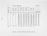
OCR Text is set to unity at the center of the first zone. The calculation begins in the third zone, downstream of the zones occupied by the flame. The farther downstream of the flame, the more conservative the estimate of destruction efficiency. The shape of the radial temperature profiles is specified by the boundary layer thickness and polynomial order. For simplicity, the temperature is assumed to be constant across the center of the furnace and to drop off linearly at one-quarter of a radius from the wall. This is a reasonable representation of the experimental temperature data. The furnace is divided into three concentric annuli whose borders are one-eighth and one-quarter of a radius from the wall. Computational time is saved by selecting a small number of annuli, at the expense of a conservative DRE prediction. The pseudo first-order rate constants used for inputs to the model were taken from the literature (Ref. 11, 12). They were derived from the fixed temperature oxidation of dilute vapors of hazardous waste in air in a quartz tube flame reactor. The rate constants are not well suited to the furnace model because they do not include an oxygen-dependent term. An oxygen concentration term was added and appropriately adjusted. Table 5 shows the important components of the computer output for the baseline case. The four tables correspond to three annuli and the overall bulk flow results. Each table shows the cumulative residence time, temperature, and mass fraction waste breakthrough, C/CQ, at the center of each zone. The overall fractional breakthrough, under the "bulk flow" heading, is simply the average of each annular contribution, weighted by the flowrate through the annulus. In this case, the postflame gases in the furnace center temperature, and mass fraction waste breakthrough, C/CQ, at the center of each zone. The overall fractional breakthrough, under the "bulk flow" heading, is simply the average of each annular contribution, weighted by the flowrate through the annulus. In this case, the postflame gases in the furnace center promote 99.93 percent DRE at Zone 10 (6.875 ft from the front wall). However, the postflame gases along the wall promote only 99.12 percent DRE at Zone 10. The bulk flow table shows that the turbulent flow boundary layer shape was calculated for the baseline case, because the bulk Reynolds number exceeded 3,000. Figure 9 shows the baseline concentration profiles at each annulus plotted against axial position. The graph shows clearly that the cold walls quench waste conversion reactions in the postflame gases in the outermost 5.5.19
Setname uu_afrc
ID 1940
Reference URL https://collections.lib.utah.edu/ark:/87278/s6cn76ff/1940