| Title |
Spatial Structure of a Confined Swirling Flow Using Planar Elastic Scattering and Laser Doppler Velocimetry |
| Creator |
Edwards, C. F.; Fornaciari, N. R.; Dunsky, C. M.; Marx, K. D.; Ashurst, W. T. |
| Publisher |
University of Utah |
| Date |
1991 |
| Spatial Coverage |
presented at Honolulu, Hawaii |
| Abstract |
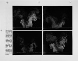
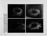
This paper reports the results of a study of the instantaneous spatial structure of a confined swirling flow after a sudden expansion. The flow chosen corresponds to the cold flow conditions of an axisymmetric laboratory-scale research furnace. The swirl number of the flow is 0.7 at the inlet plane and the expansion diameter ratio is 6:1. The flow has a center hub-to-throat diameter ratio of 1:4. Data are reported for the instantaneous spatial structure of the flow via transient planar elastic scattering imaging. This technique allows for unambiguous visualization of the spatial structure of the flow by slicing through it with a thin sheet (-1.5 mm) of light at various locations in the axial/radial and radial/azimuthal planes. By varying the time delay between introduction of the seeding material and data acquisition, features of the flow that would ordinarily be inaccessible are revealed. Laser Doppler velocimetry is used to measure the time averaged and RMS velocity components in all three coordinate directions. Using this data, we construct a model of the flow from the viewpoint of the vorticity fed into the flow and its subsequent dynamics. This viewpoint suggests different reasons for the development of the observable features of the flow and shows promise for helping to deconvolve the apparent complexity of this flowfield. |
| Type |
Text |
| Format |
application/pdf |
| Language |
eng |
| Rights |
This material may be protected by copyright. Permission required for use in any form. For further information please contact the American Flame Research Committee. |
| Conversion Specifications |
Original scanned with Canon EOS-1Ds Mark II, 16.7 megapixel digital camera and saved as 400 ppi uncompressed TIFF, 16 bit depth. |
| Scanning Technician |
Cliodhna Davis |
| ARK |
ark:/87278/s6cf9sp9 |
| Setname |
uu_afrc |
| ID |
6782 |
| Reference URL |
https://collections.lib.utah.edu/ark:/87278/s6cf9sp9 |


