| Title |
NOx Reduction Using Plasma Modified Gases |
| Creator |
Bortz, S. J.; Helfritch, D. H.; Wolfenden, V. T. |
| Publisher |
University of Utah |
| Date |
1992 |
| Spatial Coverage |
presented at Cambridge, Massachusetts |
| Abstract |
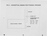
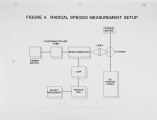
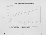
A post combustion NOx control process is currently under development by ResearchCottrell which reduces NOx emissions by utilizing the pyrolysis products of hydrocarbons and/or other gases. The process, which has been named PYRONOx, involves frrst creating the radical species in a plasma torch. The radicals are then rapidly mixed with the flue gases, which under the correct conditions can generate high levels of NOx reduction through a series of reactions similar to reburning or thermal DeNOx. This paper presents theoretical and experimental results from the development of the PYRONOx process documenting the efficiency of the plasma torch in creating the desired radicals, the results of experiments optimizing rapid mixing between the plasma and flue gases and the NOx reductions obtained over a range of operating conditions. |
| Type |
Text |
| Format |
application/pdf |
| Language |
eng |
| Rights |
This material may be protected by copyright. Permission required for use in any form. For further information please contact the American Flame Research Committee. |
| Conversion Specifications |
Original scanned with Canon EOS-1Ds Mark II, 16.7 megapixel digital camera and saved as 400 ppi uncompressed TIFF, 16 bit depth. |
| Scanning Technician |
Cliodhna Davis |
| ARK |
ark:/87278/s60p12mp |
| Setname |
uu_afrc |
| ID |
11742 |
| Reference URL |
https://collections.lib.utah.edu/ark:/87278/s60p12mp |


