Page 6

Update Item Information
Title Coal-Water Mixture Combustion and Flame Studies at TRW
Creator Roy, Dr. Gabriel ; Albright, Jack
Publisher Digitized by J. Willard Marriott Library, University of Utah
Date 1983
Spatial Coverage Akron, Ohio
Abstract Coal-water mixture (CWM) atomization and combustion characteristics were investigated. The results of this investigation show promise for using CWM as a fuel for retrofit in utility and industrial applications, and demonstrated the adaptability of the TRW coal combustor for CWM combustion. A 10 MM Btu/hr burner was developed and its geometry optimized after thorough cold-flow atomization studies. Combustion studies were carried out in a 17-inch slagging coal combustor at the TRW Fossil Energy Test Site (FETS) using CWM manufactured by the Atlantic Research Corporation (ARC). The effect of various parameters on combustion and flame stability was investigated. It was demonstrated that heavily loaded (70%) CWM can be burned with a stable flame over a wide range of stoichiometry (0.7 < <f> < 1.15) and preheat temperature (700 F < T < 1900 F) in the TRW slagging combustor. The burner designed for 10 MM Btu/hr rating operated well up to 15 MM Btu/hr and could be derated down to 5 MM Btu/hr indicating a wide load range. No flow, control or hardware related problems were experienced. Furthermore, the CWM did not cause any plugging or settling problems.
Type Text
Format application/pdf
Language eng
Rights This material may be protected by copyright. Permission required for use in any form. For further information please contact the American Flame Research Committee.
Conversion Specifications Original scanned with Canon EOS-1Ds Mark II, 16.7 megapixel digital camera and saved as 400 ppi uncompressed TIFF, 16 bit depth.
Scanning Technician Cliodhna Davis
ARK ark:/87278/s60p12js
Setname uu_afrc
ID 399
Reference URL https://collections.lib.utah.edu/ark:/87278/s60p12js

Page Metadata

Title Page 6
Format application/pdf
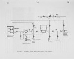
OCR Text The evaluation of coal-water mixture as a fuel was conducted in this unit. Test Cell 2 houses a 20 MWt, 6 atmospheres magnetohydrodynamic (MHD) com­bustor and will be used in the near future for testing of a 50 MW unit. In addition, a new Test Cell 3 is currently under construction, which will house a 50 MM Btu/hr (nominal) atmospheric combustor. During testing, all operating parameters are controlled and monitor­ed by a computer located in the Operations Control Room, which is linked to the combustors through satellite computers. In parallel, relevant test areas are continuously monitored by closed loop TV cameras. The com­bustion products are monitored in several locations in the combustor system by continuous emission analyzers. The flow loop used in the atomization tests were installed in a bay next to Test Cell 1. The CWM pipe line was extended to Cell 1 where the TRW slagging combustor is installed. The 17-Inch diameter combustor developed by TRW employed a vitiator as the source for preheated oxidant (air) which is generated by burning a predetermined amount of #2 fuel oil with oxygen and air in a refractory lined chamber. The slagging section of the combustor is a cylindrical confined vortex flow chamber (Figure 6). The CWM burner is located at the head-end of the combustion chamber. During combustion, as the slag layer builds up on the walls, the slag surface becomes molten, runs down the walls and flows into the water-filled tank through a slag tap. Instrumentation The test cell is fully instrumented for measurement of all required plant parameters and performance of all auxiliary equipment. A total of over 200 facility and test parameter channels were used. The test cell operation is controlled remotely by the main control room computer. The state-of-the-art control center not only controls and monitors all facility and test functions, but also provides digital and analog record of measured parameters. All test parameter measurements were presented in engineering units by on-line printer. Critical test sections were continuously monitored by video systems. Beside the facility and system parameters, also measured were the CWM, atomizer and oxidizer flow rates, heat loss from various combustor 7
Setname uu_afrc
ID 393
Reference URL https://collections.lib.utah.edu/ark:/87278/s60p12js/393