Home
Browse
Ask Us
Chat
Harmful Language Statement
Log in
Photo Archives
Advanced Search
About
Over 70,000 photos covering a variety of topics from Marriott Library Special Collections
Year
1930
1931
1932
1933
1934
1935
1936
1937
1938
1939
1940
1941
1942
1943
1944
1945
1946
1947
1948
1949
1950
1951
1952
1953
1954
1955
1956
1957
1958
1959
1960
1961
1962
1963
1964
1965
1966
1967
1968
1969
1970
TO
1930
1931
1932
1933
1934
1935
1936
1937
1938
1939
1940
1941
1942
1943
1944
1945
1946
1947
1948
1949
1950
1951
1952
1953
1954
1955
1956
1957
1958
1959
1960
1961
1962
1963
1964
1965
1966
1967
1968
1969
1970
Type
Image
100
Format
image/jpeg
100
Collection
Photo Archives
100
Filters:
Format:
"image/jpeg"
Collection Name:
"Environmental Geology in Utah"
1
-
25
of
100
<
1
2
3
4
>
Gallery view
Number of results to display per page
10
25
50
100
200
Sort by Relevance
Sort by Title A-Z
Sort by Title Z-A
Sort by Date Ascending
Sort by Date Descending
Sort by Last Modified Ascending
Sort by Last Modified Descending
Title
Date
Type
1
Portion of the East Bench along the mountain front in Salt Lake County. It has been dissected by strands of the Wasatch Fault. Since this photo was taken a housing development has been built on this terrain.
Image
2
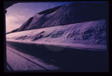
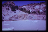
Reservoir slopes failing just upstream from dam. A failure overtopping the road would cause turbidity in the drinking water for a large city since the intake is directly downstream and in line with the current.
Image
3
Rock-debris flow from source onto road in foreground.
Image
4
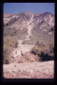
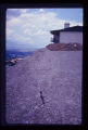
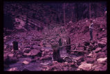
Rockfall, American Fork Canyon, February 1970. Observer stands on one of the boulders of rockfall looking across at debris fan which was washed down when aquaduct was struck and severed on the mountain side. Note height at which tree in foreground was broken off by boulder.
1970-02
Image
5
Same view showing notch in cut slope, the result of a failure onto the road soon after opening to traffic (p1274n030). Landsliding is predictable.
Image
6
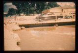
Sandbagging of Big Cottonwood Creek to confine its flow. Bridge was temporary, to span floodwaters.
Image
7
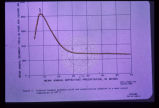
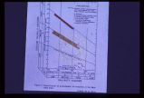
Sediment load is a factor to be considered with surface streams. This graph shows the relationship between mean annual sediment load and mean annual precipitation for the specific environment where the mean annual temperature is 40 degrees F. Other curves may be drawn for various other mean annual temperatures. Note that in this regime sediment yield is greatest at about 8 or 9 inches of precipitation. This factor must be given careful consideration when designing flood impoundment structures. The greater the sediment load the quicker the reservoir fills up.
Image
8
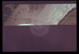
September 1970 flooding, by widespread cloudburst, of the San Juan River, seen here to occupy most of its floodplain. Bridge is only link to civilization for approximately 1,000 Navajo Indians. Note that only the left one-third of bridge has escaped attack by rising flood waters (other two-thirds appear muddy). Oblique aerial view. Most of Utah is subject to cloudburst flooding from April to September. Cloudbursts are of short duration and high intensity.
1970-09
Image
9
Slide of fill material in high, steep fill slope on Salt Lake City's North Bench.
Image
10
Standard Salinity Hazard chart for groundwater from all aquifers in the Bear Lake area. This chart is used for agricultural purposes. Note that all waters sampled are satisfactory for all plant types.
Image
11
Steep, high, artificial fill slopes in or near the Wasatch Fault Zone. Downslope from these fills lie dense residential developments. Atop these fills are residences. How may these earth materials be expected to react to seismic vibrations?
Image
12
Surficial or shallow ground water is subject to pollution from buried solid wastes. Leaching of the wastes can occur in time. This excavation is for a land fill operation where ground water was encountered at a depth of less than 6 feet.
Image
13
Swelling of clay soil as it takes on additional moisture heaved up this garage floor and cracked it.
Image
14
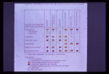
Table listing types of geologic terrain in the Bear Lake area and their limiting factors for fluid waste disposal by individual home systems. Yellow indicates caution is required and red indicates a critical situation.
Image
15
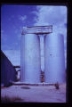
These twin tanks deverge from bottom to top. Differential settling of their foundations caused this.
Image
16
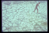
This pattern of cracking in the unconsolidated clays and silts from ancient Lake Bonneville is the result of shrinking upon drying. Geologic material may be considered as dynamic, not static, and may deform readily under stress. Deformation may damage or destroy structures placed upon this type of geologic material.
Image
17
This water storage reservoir has failed; it was placed improperly upon a stratum of gypsum (white layers in photo) which partially dissolved.
Image
18
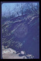
Undisturbed hillside failing because of lateral and vertical erosion by creek. Debris is continuously removed from toe of sliding hillside by the creek.
Image
19
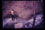
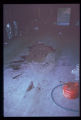
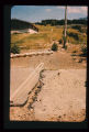
Upstream from the monument was this scene in May 1969. Broken tree trunks and picnic table (beneath feet of observer in photo) recently re-exposed from under 8 feet of debris.
1969-05
Image
20
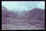
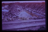
View across City Creek Canyon in Salt Lake City, showing amphitheater-like appearance of ancient landslide. Houses are short distance to left of landslide.
Image
21
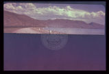
View across the north end of Bear Lake looking east at the truncated spurs, geomorphologic evidence of the Bear Lake Fault.
Image
22
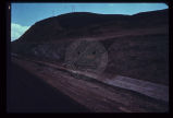
View along the highway traffic lanes and the dam abutment at the newly created cut slope.
Image
23
Dropping of street which crossed old landslide failure plane. Note break in slope towards distance in line with fresh scarplet across street. Utility pole is seated along the slide plane.
Image
24
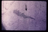
Engineering plan for a proposed reservoir in Salt Lake City. Note the anomalous contour spacing under the arrow. This indicates that the hillside has slid in the past. Construction of a reservoir here would inundate the toe of an ancient landslide and destroy the balance and stability of the weak landslide mass.
Image
25
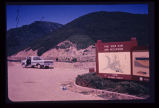
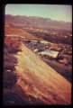
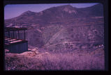
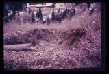
Erosion caused by release of water on severance of aquaduct in foreground. Timpanogas Cave National Monument Visitor Center lies at bottom of canyon.
Image
1
-
25
of
100
<
1
2
3
4
>