| OCR Text |
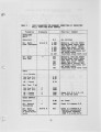
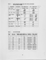
Show glass surface temperature of 26000 F (1700 K). In the second set of calculations, a constant temperature of 24200 F (1600 K) was assumed to occur someway into the glass bath. A uniform effective ratio of conductance to thickness of k/s = 0.612 kW / m2 K was used in order to calculate heat transfer through the upper glass bath layer. This value was determined so, that the area weighted glass surface temperatures averaged 2600uF (1700 K) for the baseline 02 firing configuration. In both set of calculations, an effective glass surface emissivity of 0.88 was utilized. Major Operating Conditions and Case Definitions Major operating conditions of the end-section considered for air and 02-Firing are listed in Table 2. The gross fuel heat input of 12.16 MMBtU/hr (3563 kW) utilized for air firing is related to the gas burners of one port. The fuel heat input cited for 02 firing relates to half of the fuel input for 02 burner A5 plus the heat input for 02 burner A6 (see Fig. 4). The air preheat of 23300 F (1550 K) utilized for conventional air firing corresponds to average measured values for the burner load considered. Similarly, the 02 concentrations of 2.2 Vol. %, dry corresponds to average 02 concentrations measured during the flue gas cycle in the upper regenerator. All cases studied in this paper are defined in Table 3. The 3-D modeling effort comprises five major cases. However, four of these cases are also presented for a variation, in which the glass surface temperatures are calculated from a simple model rather than prescribed to be constant. The cases with constant glass surface temperatures are numbered 1.0 through 5.0, and the cases with variable surface temperatures 1.1 through 5.1. Case 1 is the case conducted for conventional air combustion and serves, in the context of this study, as bench mark for performance comparisons with predictions of Cases 2 through 5 for the 02-firing system. The firing arrangement for Case 1 is shown in Fig. 4. Case 2 through 5 were performed for a latitudinal arrangement of two oxygen burners as shown in Fig. 4. The burners are numbered A5 and A6. A5 fires along the centerline between the two last ports of the glass furnace (Ports 4 and 5). A6 fires in opposite direction with burner axis located in the plane which divides the breast wall section between last port and the bridge wall in half. Case 2 with equal burner load A5/A6 was performed to I)ptimiz~ the 02 configuration. All other oxygen cases were performed for burner load ratio A5/A6 of 3.71. Case 3 is defined 10 |