| OCR Text |
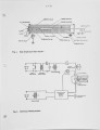
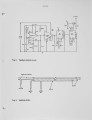
Show 1.7.3 a thermocouple probe to measure the temperature along the axis of the reactor, or a sample probe to withdraw gas samples. Each of these probes can be moved axially, allowing the determination of temperature and composition profiles along the centerline of the reactor. The flow metering system contains separate rotameters (Matheson models 601, 603 and 605) for hydrogen, oxygen, nitric oxide (supplied commercially in a mixture of 5% NO in helium), ammonia, and argon or helium. The data were evaluated with the aid of calibration curves based on argon [5], using the standard conversion formula Qg/Qa = Ma/Mg» where Q = flow rate in standard litres per minute, M = molecular weight, subscript a denotes argon, and subscript g denotes the gas being metered. The NO was further diluted by mixing the 5% NO - helium mixture with argon or helium. The hydrodynamic entry length x for flow in tubes is given approximately by x / d s Re/20, where d is the tube diameter and Re the Reynolds number. At a typical temperature of 1000 K, the Reynolds number is about 200, and the hydrodynamic entry length is on the order of 25 cm. At the temperatures of interest, the hydrogen-oxygen mixture is within its explosion regime. As a result, the hydrogen and oxygen are expected to react immediately upon being heated. Fig. 2 show a diagram of the electrical system used to heat the reactor. This system also was designed by Roby C5 3. The reactor is divided into five heating zones, each of which is served by a separate heating circuit providing a maximum of 40 A alternating current derived from a 220 VAC single phase line. This supplies a maximum of 1.8 kW per zone. The current supplied to each zone is controlled by a triac built into a thermocouple feedback control circuit. There is one thermocouple for each heating zone. The circuit diagram of the feedback control unit is shown in Fig. 3. If the zone temperature is below its set point, a short gate pulse is sent from the control circuit to the triac. This pulse is synchronized with the zero crossing of the AC current. The current to the power circuits is varied continuously by varying the phase angle of the gate pulse. Measurements with the thermocouple probe showed that the axial temperature variations over the length of the reactor were within 15 K from the average. This was considered acceptable for the purposes of the present work. It was verified that turning on the gas flow through the reactor did not significantly change the reactor temperature. For further details of the control system, reference is made to Roby [53. Fig. 4 shows a sketch of the sampling probe [53. The probe has a length of 100 cm, an outer diameter of 0.32 cm (3/8"), and an inner diameter of 0.11 cm (1/8"). It is provided with a water jacket that serves to cool the probe and to quench the chemical reactions [5,6]. One end of the probe is used to aspirate the gases from inside the reactor. The other end has a small chamber with a rubber septum. Samples are taken out through the septum using a Hamilton 10 cc gas locking syringe. The flow through the probe is maintained by a connection to the vacuum pump. This flow is regulated such that the pressure in the probe is 50 torr |