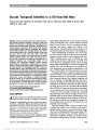
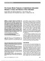
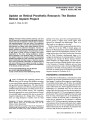
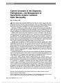
| OCR Text |
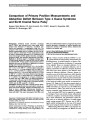
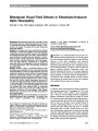
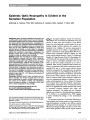
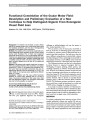
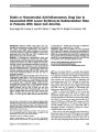
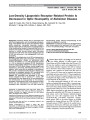
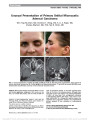
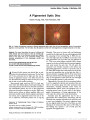
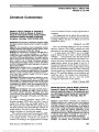
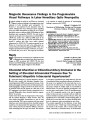
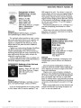
Show Update on Retinal Prosthetic Research: The Boston Retinal Implant Project Joseph F. Rizzo III, MD Abstract: The field of retinal prosthetic research, now more than 20 years old, has producedmany high-quality technical options that have the potential to restore vision to patients with acquired disease of the outer retina. Five companies have performed Phase I clinical trials demonstrating that blind patients can reliably report basic elements of visual percepts induced by electrical stimulation. However, at present patients and observers generally do not consider the results to be useful enough in the performance of tasks of daily living to justify the risks of surgery and chronic implantation or the costs. Having developed a wireless device implanted in the subretinal space, the Boston Ret-inal Implant Project has focused its efforts on developing scalable technologies to create a hermetic device that can deliver individually controlled pulses of electrical stimula-tion to each of hundreds of electrodes. An advanced device with such attributes will be needed to justify the risks of implantation. An assessment of long-term biocompatibility for all devices remains to be done. Journal of Neuro-Ophthalmology 2011;31:160-168 doi: 10.1097/WNO.0b013e31821eb79e 2011 by North American Neuro-Ophthalmology Society Avariety of biological and engineering advances now offer some hope for patients with blindness secondary to outer retinal disease, especially retinitis pigmentosa (RP) and age-related macular degeneration. The retinal implant is designed to stimulate nerve fibers that had been properly established during development and which survive the de-generation of more proximal neurons. This compelling theoretical opportunity to restore visual function, however, is inextricably linked to potential risks that are incurred by long-term implantation of a foreign device. Visual pros-theses are being developed to interface with the visual pathway in the retina, optic nerve, lateral geniculate body, and the primary or higher visual cortical regions. Each approach has advantages and disadvantages. There is no clear benefit to one approach or the other. The first attempt to build a visual prosthesis dates back to the 1970s (1). In the late 1980s, 2 research groups, one based at the Massachusetts Eye and Ear Infirmary/Harvard Medical School and the Massachusetts Institute of Tech-nology and the other at the North Carolina State University and the Duke University, simultaneously began to in-vestigate the development of a retinal prosthesis. The former consortium now includes the Boston Veterans Adminis-tration Hospital as an integral partner. The latter consor-tium moved to the Johns Hopkins Medical School and then to the University of Southern California and now forms a nucleus of activity that is tied to the Second Sight Medical Corporation. The field of retinal prosthetics now includes more than 15 research groups (5 of which are partners with corporate ventures) in 6 countries (2-7). ENGINEERING CONSIDERATIONS To provide vision to blind patients, a microelectronic retinal prosthesis in its most basic operational form must 1) capture visual images, 2) transform those images into a spatial pattern of controlled electrical pulses, and 3) deliver the controlled electrical pulses to the retina. Two basic approaches have been used to achieve these aims. The first approach is based on the implantation of a photodiode array that can convert the energy of light from the visual scene into electrical pulses that stimulate the retina (8-13). The second approach is based on the placement of the means for imaging the visual scene away from the retina, which requires the use of hard-wired con-nections to deliver the electrical pulses to stimulating elec-trodes that are implanted on the epiretinal or subretinal surface (14,15). The former approach is perhapsmore elegant and reminiscent of how the eye actually works, but it requires implantation into the eye of more sophisticated electronics, which would increase the risk of failure of components that could not easily be fixed or replaced (14,15). Section Editors: Grant T. Liu, MD Randy H. Kardon, MD, PhD Departments of Veterans Administration and Ophthalmology, Harvard Medical School and the Massachusetts Eye and Ear Infirmary, Boston, Massachusetts. Address correspondence to Joseph F. Rizzo III, MD, Department of Ophthalmology, Massachusetts Eye and Ear Infirmary, 243 Charles Street, Boston, MA 02458; E-mail: joseph_rizzo@meei.harvard.edu 160 Rizzo: J Neuro-Ophthalmol 2011; 31: 160-168 State-of-the-Art Review Copyright © North American Neuro-Ophthalmology Society. Unauthorized reproduction of this article is prohibited. BOSTON RETINAL IMPLANT PROSTHESIS Design After nearly a decade of working on the epiretinal surface, the Boston Retinal Implant Project (BRIP) chose a sub-retinal approach to implant the electrode array (16). Our prosthetic designs have been motivated by the following principles: 1. Minimize disruption of the anatomy of the eye 2. Use a minimally invasive surgical method to implant the device 3. Minimize the amount and sophistication of the elec-tronic components implanted into the eye and orbit 4. Use an ultrathin flexible substrate that can bend to match the contour of the ocular tissues 5. Use wireless technology to provide a functional connection between the external and the implanted components 6. Use means to individually control and to individually adjust the stimulation parameters to each electrode based on patient feedback. The first 4 of these design principles should enhance the biocompatibility of our device. The third principle also should improve the reliability of our device by retaining much of the electronic functionality outside of the body. The use of wireless technology (the fifth principle) avoids the need for a connector cable, which is notoriously prone to failure. The sixth principle is founded on our belief that generation of useful visual images will be achieved only through iterative testing based on the feedback from each patient. Our first-generation device was developed for pre-liminary experiments in animals (Fig. 1), and the second-generation device is intended for use in humans (Fig. 2). A frequent point of comparison among designs from different research groups or companies is the number of stimulating electrodes. Of those devices currently implanted in humans, the Second Sight device has 60 stimulating electrodes and the Retina Implant AG device has about 1,500 photodiode elements, which are not individually controllable. Our team is nearing completion of a device with more than 200 individually controlled stimulating electrodes. Many simulation studies with normally sighted subjects have offered predictions regarding how many FIG. 1. Images of the first-generation (left panels) and the second-generation (right panels) retinal prosthetic devices developed by the BRIP. The photograph of the first-generation device shows our custom-designed IC (yellow arrow, upper left panel), an upgraded version of which is housed within the hermetic environment of a titanium case in our second-generation device (white arrow, lower right panel). The ocular positioning of the first-generation device is shown in the lower left panel. The second-generation device, which we will be used for future human testing, includes a glasses-frame structure to support a small camera (red arrow, upper right panel) that collects visual images. The second-generation device also includes a radio frequency (RF) coil positioned around the limbus (yellow arrow, lower right panel), which receives wireless transmission of power and visual signal from a ‘‘primary'' RF coil embedded within the glasses-frame. In both designs, the stimulating electrode array is the only component that has to be placed within the eye (red arrows, both lower images). Rizzo: J Neuro-Ophthalmol 2011; 31: 160-168 161 State-of-the-Art Review Copyright © North American Neuro-Ophthalmology Society. Unauthorized reproduction of this article is prohibited. stimulating electrodes would be needed to perform tasks like navigation and reading (17-21), but the optimal number of electrodes to achieve a particular level of visual function will have to be reconciled through experimental studies with blind humans who have received a prosthesis. Meanwhile, plans for developing an ever-larger number of electrodes are fueled by the availability of sophisticated engineering methods and the belief that more electrodes will provide better vision. Almost the entire BRIP device lies outside of the eye, which minimizes the potential for problems with bio-compatibility that are more likely to arise for components placed inside of the eye (Fig. 2). The external placement of the ‘‘stimulating chip'' (our custom-designed integrated circuit [IC]) also allows us to provide hermetic encapsula-tion for the IC by using a titanium enclosure, which would be impractical for use inside of the eye. Titanium has been used reliably for decades to protect the electrical components of cardiac pacemakers, and we have modified this technology to create a miniaturized assembly. For the purpose of conducting animal studies, the BRIP made a 15-channel device that provides long-term tests of hermeticity (16). Each stimulating channel requires a hard-wired connection, called a ‘‘via,'' that must emerge from the confines of the titanium enclosure. These exit points are vulnerable to leakage of water vapor and sodium ions, which even in minute quantities would destroy the transistors. The plan to use hundreds of electrodes for our human-quality device is perhaps the greatest technical challenge that we face, and it has required the customization of an emerging technology to provide the larger number (and higher density) of feedthrough vials for our application. The need to develop hundreds of stimulation channels is a good example of how the demanding needs for a visual prosthesis are pushing the state-of-the-art for the development of other implantable microelectronic devices. By comparison, for instance, the highest number of channels for any other neural prosthetic device is 32, which is found in one embodiment of a cochlear prosthesis. Most deep brain devices, like those used to treat Parkinson disease, provide only 4 electrodes. The most delicate engineering component in a retinal prosthesis is the part that contacts the retina. In the BRIP approach, only the stimulating electrode array is placed into the eye-into the subretinal space. This placement is achieved by passing the array through the sclera behind the eye (Fig. 3). The device that enters the eye is made of plastic (‘‘polyimide'') of only 10 mm thickness. Because of its flexi-bility, it can bend to match the curvature of the delicate retina without generating a spring-like ‘‘restorative'' force that might damage the host tissue. This device is made by using cus-tomized microfabrication technology to embed themicrowires and form the stimulating electrodes (Fig. 4). Microfabricated devices like these can be designed tomeet specifications for any reasonable number and density of electrodes, which can be shaped into practically any 2- or 3-dimensional geometry. FIG. 2. Pictorial overview of our ab externo surgical approach. A. Creation of a scleral flap through the back wall of the eye. B. Raising of a retinal bleb (asterisk) by injecting fluid under the retina. The elevated bleb serves to reduce the potential of retinal damage when the electrode array is inserted. C. Insertion of a custom surgical tool (yellow mem-brane) that serves as a guide for the subsequent insertion of the electrode array. D. Digital image of the insertion of the electrode array (arrow) through the scleral flap and under the retina, which has returned to its original position. 162 Rizzo: J Neuro-Ophthalmol 2011; 31: 160-168 State-of-the-Art Review Copyright © North American Neuro-Ophthalmology Society. Unauthorized reproduction of this article is prohibited. Surgical Implantation The surgery to implant an electrode array on the epiretinal surface (22,23) is easier than that used to implant an array in the subretinal space (13,24-26), but the epiretinal approach creates a greater challenge to achieve a close and conformal alignment of the electrode array to the retinal surface (27). The most common method to affix an epiretinal implant uses a ‘‘tack''(23,28,29), which is prone to displacement and which tends to induce gliosis that potentially interposes a high resistive barrier to electrical stimulation. The risk of gliosis limits the number of tacks that can be used (typically only 1 or perhaps 2). Although a tack can effectively secure the electrode array near the retina at the site of insertion, the remainder of the array tends to vault away from the retina. Even minor elevation of the electrode array will cause a significant elevation in the stimulation thresholds (30,31), which increases the risk of damage to the retina and to the electrodes themselves. The epiretinal approach also becomes increasingly more challenging with attempts to use electrode arrays with larger areas (to provide more stimulating elec-trodes) because the mismatch between the 2-dimensional array and 3-dimensional retina accentuates at larger dimensions. (Although a similar geometrical mismatch is relevant for the subretinal approach, the pressure dynamics within the subretinal space enable a seemingly conformal alignment of our thin films over a relatively wide area, up to 5 mm in diameter.) These concerns contributed to our decision long ago to use a subretinal approach. We developed a surgical method that required only a single slit in the back of the eye to introduce the electrode array. Once in place, it typically retains a tight apposition to the undersurface of the retina without the need for tacks or adhesives (Fig. 5). This stability is achieved in the absence of FIG. 3. Microfabrication steps used by our team to produce polyimide arrays with iridium oxide-coated electrodes. Top: Upper left image shows the schematic layout of our first-generation device. Right image shows a 4$ silicon wafer that contains numerous electrode arrays of varying shapes. Bottom: Left image shows a magnified view of the distal end of the electrode array with gold wire traces and 1 electrode coated with iridium oxide (large, round, brown object). Right image shows a magnified view of surface of electrode coated with iridium oxide 1 year after electrical pulsing in saline solution, which provides evidence of electrical stability. Rizzo: J Neuro-Ophthalmol 2011; 31: 160-168 163 State-of-the-Art Review Copyright © North American Neuro-Ophthalmology Society. Unauthorized reproduction of this article is prohibited. significant fibrosis around the arrays, which has allowed us to safely and easily remove arrays that had been chronically implanted into the subretinal space of mini pigs (32). Our methods allowed implantation of a 5-mm-diameter electrode array, the largest surface area of an array safely implanted into a living eye (33). Our array should provide vision over roughly 14 of visual angle to assist in navigation through unfamiliar environments. Biocompatibility Biocompatibility includes the biological responses that oc-cur secondary to the surgery, foreign materials, and effects of electrical stimulation. When we began our project, there was no evidence that foreign material could be safely implanted adjacent to the retina for long periods. We surveyed 6 materials as substrates for the electrode array (34). All caused some degree of damage or incited some degree of response to the foreign device, but none were severe enough to produce encapsulation of the implanted device, for instance. Other groups have also shown similarly favorable outcomes with foreign materials placed on the epiretinal surface. COLLECTIVE ACHIEVEMENTS IN THE VISUAL PROSTHETIC FIELD The basic goals of capturing visual information and de-livering electrical stimulation to the retina have been FIG. 4. Images of 2 different types of electrode arrays, manufactured by the Boston Retinal Implant Project. A. Fundus photograph of an electrode array 3 months after implantation in a rabbit retina. B. Optical coherence tomography of the same electrode array seen as a highly reflective (falsely colored) red line under the retina. The electrode array is tightly apposed to the retina over the length of the array. C. Ten-micrometer microfabricated polyimide array with 100 elec-trodes. D. Fundus photograph of the same array 3 months after implantation in a pig retina. This is the widest electrode array ever implanted into the subretinal space of an animal. FIG. 5. Histology of pig retina 3 months after subretinal implantation of coated nonelectronic implants (seen as yellowish fairly flat structures under the retina). A. Relatively little anatomical alteration following implantation of Parylene. B. Two retinal pigment epithelial (RPE) cells (1 shown by arrow) have clumped over an implant made of polyimide, which is our favored substrate material. Both implants were 0.5 3 0.5 3 10 mm (hematoxylin and eosin, 320). 164 Rizzo: J Neuro-Ophthalmol 2011; 31: 160-168 State-of-the-Art Review Copyright © North American Neuro-Ophthalmology Society. Unauthorized reproduction of this article is prohibited. achieved by numerous groups. Many different types of implanted devices are well tolerated even after prolonged implantation into the eye. These efforts have provided in-sights into how neurons respond to electrical stimulation and how these responses differ from those generated by the normal photic stimulation (30,35-44). These achievements should not be construed to suggest that these areas of investigation are complete or that they will enable success in restoring vision to blind patients. There have been several problems associated with human implants, including multiple cases of extrusion of implanted devices through the conjunctiva, dislodging of retinal tacks, endophthalmitis, hypotony, and failure of hermetic pro-tection of the implanted electronic components, which rendered the devices useless. Five research groups have been involved in sustained efforts to develop a retinal implant (Table 1). A sixth group, Optobionics, Inc, put in a strong effort but declared bankruptcy after implantation of 20 patients with a sub-retinal prosthesis (45). The company concluded that its successes were not the result of electrically induced activa-tion of neuronal responses that propagate to the brain. Rather, a ‘‘trophic'' effect was identified, which although substantiated by careful scientific work (46-48), called into question the value of the device. The most fundamental outcome of this collective work has been the reporting of the psychophysical threshold for electrical stimulation, that is, the amount of electrical charge required for patients to reliably report a visual sensation. The activation threshold is the most important single parameter to assess the potential safety of the long-term use of these devices and to design the power budget for a prosthetic system (49-51). The thresholds, which have been obtained in patients who were severely blind from RP, were initially found to be relatively high, perhaps too high for safe electrical stimulation with the platinum-type electrodes that were being used given the safety charge limits of these electrodes. More recently, measured thresholds have been substantially lower and more encouraging (in the range of a few microcoulombs per square centimeter or less). However, thresholds have varied considerably across patients, across electrodes within a single patient, and over time (49,52,53). The issue of long-term safety has yet to be reconciled. Visual acuities have been reported to be as good as 20/1,000, which would provide a significant improvement over the baseline level of ‘‘light perception'' in implanted patients (54). More recently, obtained with a 16-channel device, visual acuity without the benefits of visual scanning has been reported as equal to the physical spacing of the stimulating electrodes (55). This result has supported a belief that more electrodes would translate into higher quality spatial perception, but this outcome is far from certain. The uncertainty about the potential visual outcome for a given number of electrodes relates to the fact that the electrical fields emanate in complex ways from the elec-trodes, with patterns of constructive and destructive in-terference, like the ripples in water caused by the impact of a rock. This phenomenon creates uncertainty about the patterns of activation of neurons that govern the quality of perception. Studies also demonstrated that implanted patients can localize the quadrant of a large stimulus, identify the direction of moving lines, and identify some common objects like forks and cups (29). The perception of brightness has been shown to correlate with the amount of electrical current used for stimulation, although con-siderable variability was found in 1 of the 2 subjects (56). Perhaps the most encouraging results have been reported by the Retina Implant AG company (Tubingen, Germany). After 1 week of implantation, a patient was judged to be capable of reading letters and words similar in size to those in newspaper headlines (57,58). If these results, derived by subretinal stimulation, are sub-stantiated by further testing, the retinal prosthetic tech-nology would have the potential to improve the quality of life for severely blind patients. UNMET GOALS Several requirements for long-term success have yet to be met. There must be scientifically convincing evidence that the induced vision can improve quality of life for blind patients. There must be solid data on the safety of these devices, which will require surveillance of a large number of implanted patients. There must be further improvements in the engineering of these devices to provide a larger number of stimulating electrodes that can be interfaced more closely to the retinal neurons. Finally, there must be more knowledge of the neuroscience related to more effective stimulus paradigms, encoding of visual information from TABLE 1. Retinal implant projects at or near the phase of human testing Company Location Position of Implant Boston Retinal Implant Group Boston, MA Subretinal Second Sight Sylmar, CA Epiretinal Retina Implant AG Tubingen, Germany Subretinal Intelligent Medical Implants Bonn, Germany Epiretinal Epi-Ret Bonn, Germany Epiretinal Rizzo: J Neuro-Ophthalmol 2011; 31: 160-168 165 State-of-the-Art Review Copyright © North American Neuro-Ophthalmology Society. Unauthorized reproduction of this article is prohibited. the retina to the brain, and plasticity of the visual cortex following blindness. There is still relatively little in-formation about the physiology of degenerated retinas, but the need to understand these responses for the application of retinal prostheses has led to a very substantial increase in interest in this question (36,39,40). CAN IMPROVED PSYCHOPHYSICAL RESULTS BE OBTAINED FROM BLIND HUMANS IMPLANTED WITH A RETINAL PROSTHESIS? Vision is a complex and nuanced sensation compared to hearing, and it will undoubtedly be harder to create useful vision that it was to create useful hearing with cochlear prosthetic devices. There are several impediments to im-proving vision with such electrical implants. Electrical stimulation tends to activate retinal neuronal pathways indiscriminately, although we and others have discovered strategies to favorably bias the stimulation (30,44,59,60). Indiscriminate stimulation confounds any strategy to create useful vision. Loss of photoreceptors causes significant ‘‘reorganization'' of the retina that will complicate the attempt to create predictable visual percepts (61,62). Visual cortical changes also occur following loss of retinal input (63,64). The extent to which these cortical changes might help or hinder the interpretation of the percepts generated by artificial electrical stimulation is unknown. WHAT CAN PATIENTS BE TOLD? The results of long-term testing of retinal implants in blind humans look promising. To properly consider the risk-to-benefit ratio, one would have to know as much detail about the complications as about the widely reported psycho-physical outcomes. Such proper consideration cannot be carried out because the complications that have occurred have not been fully reported in public forums, mostly be-cause the testing has been performed by companies that face the dilemma that reporting of untoward events might compromise the commercial potential of their product. At this stage of the investigation, there is not enough published evidence to offer comprehensive and unbiased advice to patients. Given this reality and the fact that the status of each group in the field is constantly changing, general recommendations of what advice might be given to in-terested patients are difficult to provide. Any serious con-sideration of becoming a recipient of a visual prosthesis must be grounded in reflection of the up-to-date outcomes from each group in the field. Representatives from the groups listed in Table 1 can discuss the status of their work and the relative merits of their approach. The interested reader also might access the Web site of each group, which provides descriptions of the current activities and contact information. THE DIRECTION OF THE BRIP Our group decided long ago not to begin chronic human implants until we had developed the technology to expand the number of stimulation channels to above 200, a number that might provide functionally ‘‘useful'' vision to blind patients, like the ability to navigate safely in an unfamiliar environment. The technology needed to produce such a device includes the means to transmit sufficient power to support stimulation across the larger number of electrodes and the means of providing the hermeticity for the ICs and microwires that course through the ultrathin membrane that enters the eye. Such long-term development efforts are facilitated by the freedom to flexibly pursue technical sol-utions, the timetable of which is unpredictable. The value of retaining the independence to decide on an appropriate time to begin human implantation is the primary reason that our group has delayed a corporate strategy to develop this technology. Having implanted wireless devices in laboratory animals for 2 years, we have begun to collect the necessary ‘‘pre-clinical'' tests that are required by the Food and Drug Administration to obtain the Investigational Device Ex-emption that is needed before human testing can begin. Our initial human studies will be conducted with a device that will have more than 200 electrodes, which we anticipate will provide more useful vision for blind patients, although the primary intent of Phase I testing will be ‘‘safety.'' The BRIP believes that our subretinal approach and that our means to discretely control stimulation across a large number of channels will prove to be advantageous in comparison to other approaches. REFERENCES 1. Rizzo J, Tombran-Tink J, Barnstable CJ. Visual Prosthesis and Ophthalmic Devices: New Hope in Sight. Visual Cortex Prostheses. New York, NY: Humana Press, 2007:160-161. 2. Rizzo JF III, Wyatt J, Humayun M, de Juan E, Liu W, Chow A, Eckmiller R, Zrenner E, Yagi T, Abrams G. Retinal prosthesis: an encouraging first decade with major challenges ahead. Ophthalmology. 2001;108:13-14. 3. Dowling J. Current and future prospects for optoelectronic retinal prostheses. Eye. 2009;23:1999-2005. 4. Loewenstein JI, Montezuma SR, Rizzo JF III. Outer retinal degeneration: an electronic retinal prosthesis as a treatment strategy. Arch Ophthalmol. 2004;122: 587-596. 5. Thanos S, Heiduschka P, Stupp T. Implantable visual prostheses. Acta Neurochir Suppl. 2007;97(pt 2):465-472. 6. Weiland JD, Liu W, Humayun MS. Retinal prosthesis. Annu Rev Biomed Eng. 2005;7:361-401. 7. Margalit E, Maia M, Weiland JD, Greenberg RJ, Fujie GY, Torres G, Piyathaisere DV, O'Hearn TM, Liu W, Lazzi G, Dagnelie G, Scribne DA, de Juan E Jr, Humayun MS. Retinal prosthesis for the blind. Surv Ophthalmol. 2002;47: 335-356. 8. Asher A, Segal WA, Baccus SA, Yaroslavsky LP, Palanker DV. Image processing for a high-resolution optoelectronic retinal prosthesis. IEEE Trans Biomed Eng. 2007;54(pt 1): 993-1004. 9. Loudin JD, Simanovskii DM, Vijayraghavan K, Sramek CK, Butterwick AF, Huie P, McLean GY, Palanker DV. 166 Rizzo: J Neuro-Ophthalmol 2011; 31: 160-168 State-of-the-Art Review Copyright © North American Neuro-Ophthalmology Society. Unauthorized reproduction of this article is prohibited. Optoelectronic retinal prosthesis: system design and performance. J Neural Eng. 2007;4:S72-S84. 10. Kim ET, Kim C, Lee SW, Seo JM, Chung H, Kim SJ. Feasibility of microelectrode array (MEA) based on silicone-polyimide hybrid for retina prosthesis. Invest Ophthalmol Vis Sci. 2009;50:4337-4341. 11. Palanker D, Vankov A, Huie P, Baccus S. Design of a high-resolution optoelectronic retinal prosthesis. J Neural Eng. 2005;2:S105-S120. 12. Gekeler F, Zrenner E. [Status of the subretinal implant project. An overview]. Ophthalmologe. 2005;102: 941-949. 13. Gekeler F, Szurman P, Grisanti S,Weiler U, Claus R, Greiner TO, Volker M, Kohler K, Zrenner E, Bartz-Schmidt KU. Compound subretinal prostheses with extra-ocular parts designed for human trials: successful long-term implantation in pigs. Graefes Arch Clin Exp Ophthalmol. 2007;245:230-241. 14. Mokwa W, Goertz M, Koch C, Krisch I, Trieu HK, Walter P. Intraocular epiretinal prosthesis to restore vision in blind humans. Conf Proc IEEE Eng Med Biol Soc. 2008;2008: 5790-5793. 15. Alteheld N, Roessler G, Walter P. Towards the bionic eye-the retina implant: surgical, opthalmological and histopathological perspectives. Acta Neurochir Suppl. 2007;97(pt 2):487-493. 16. Shire DB, Kelly SK, Chen J, Doyle P, Gingerich MD, Cogan SF, Drohan WA, Mendoza O, Theogarajan L, Wyatt JL, Rizzo JF. Development and implantation of a minimally invasive wireless subretinal neurostimulator. IEEE Trans Biomed Eng. 2009;56:2502-2511. 17. Dagnelie G, Keane P, Narla V, Yang L,Weiland J, Humayun M. Real and virtual mobility performance in simulated prosthetic vision. J Neural Eng. 2007;4:S92-S101. 18. Chen SC, Hallum LE, Suaning GJ, Lovell NH. A quantitative analysis of head movement behaviour during visual acuity assessment under prosthetic vision simulation. J Neural Eng. 2007;4:S108-S123. 19. Chen SC, Hallum LE, Suaning GJ, Lovell NH. Psychophysics of prosthetic vision: I. Visual scanning and visual acuity. Conf Proc IEEE Eng Med Biol Soc. 2006;1:4400-4403. 20. Sommerhalder J, Rappaz B, de Haller R, Fornos AP, Safran AB, Pelizzone M. Simulation of artificial vision: II. Eccentric reading of full-page text and the learning of this task. Vision Res. 2004;44:1693- 1706. 21. Sommerhalder J, Oueghlani E, Bagnoud M, Leonards U, Safran AB, Pelizzone M. Simulation of artificial vision: I. Eccentric reading of isolated words, and perceptual learning. Vision Res. 2003;43:269-283. 22. Gerding H. A new approach towards a minimal invasive retina implant. J Neural Eng. 2007;4:S30-S37. 23. Guven D, Weiland JD, Fujii G, Mech BV, Mahadevappa M, Greenberg R, Roizenblatt R, Qui G, Labree L, Wang X, Hinton D, Humayun MS. Long-term stimulation by active epiretinal implants in normal and RCD1 dogs. J Neural Eng. 2005;2: S65-S73. 24. Sachs HG, Gekeler F, Schwahn H, Jakob W, Kohler M, Schulmeyer F, Marienhagen J, Brunner U, Framme C. Implantation of stimulation electrodes in the subretinal space to demonstrate cortical responses in Yucatan minipig in the course of visual prosthesis development. Eur J Ophthalmol. 2005;15:493-499. 25. Sachs HG, Schanze T, Brunner U, Sailer H, Wiesenack C. Transscleral implantation and neurophysiological testing of subretinal polyimide film electrodes in the domestic pig in visual prosthesis development. J Neural Eng. 2005;2: S57-S64. 26. Sachs HG, Schanze T, Wilms M, Rentzos A, Brunner U, Gekeler F, Hesse L. Subretinal implantation and testing of polyimide film electrodes in cats. Graefes Arch Clin Exp Ophthalmol. 2005;243:464-468. 27. Husain D, Loewenstein JI. Surgical approaches to retinal prosthesis implantation. Int Ophthalmol Clin. 2004;44: 105-111. 28. Tunc M, Cheng X, Ratner BD, Meng E, Humayun M. Reversible thermosensitive glue for retinal implants. Retina. 2007;27:938-942. 29. Yanai D, Weiland JD, Mahadevappa M, Greenberg RJ, Fine I, Humayun MS. Visual performance using a retinal prosthesis in three subjects with retinitis pigmentosa. Am J Ophthalmol. 2007;143:820-827. 30. Jensen RJ, Rizzo JF III, Ziv OR, Grumet A, Wyatt J. Thresholds for activation of rabbit retinal ganglion cells with an ultrafine, extracellular microelectrode. Invest Ophthalmol Vis Sci. 2003;44:3533-3543. 31. Jensen R, Ziv O, Rizzo J. Responses of rabbit retinal ganglion cells to electrical stimulation with an epiretinal electrode. J Neural Eng. 2005;2:S16-S21. 32. Chen J, Shah HA, Herbert C, Loewenstein JI, Rizzo JF III. Extraction of a chronically implanted, microfabricated, subretinal electrode array. Ophthalmic Res. 2009;42: 128-137. 33. Chen J. Surgical Methods for Large Sub-Retinal Prosthetic Implantation. Fort Lauderdale, FL: ARVO, 2007. 34. Montezuma SR, Loewenstein J, Scholz C, Rizzo JF III. Biocompatibility of materials implanted into the subretinal space of Yucatan pigs. Invest Ophthalmol Vis Sci. 2006;47: 3514-3522. 35. Jensen RJ, Ziv OR, Rizzo JF III, Scribner D, Johnson L. Spatiotemporal aspects of pulsed electrical stimuli on the responses of rabbit retinal ganglion cells. Exp Eye Res. 2009;89:972-979. 36. Jensen RJ, Rizzo JF III. Activation of retinal ganglion cells in wild-type and rd1 mice through electrical stimulation of the retinal neural network. Vision Res. 2008;48:1562-1568. 37. Jensen RJ, Rizzo JF III. Responses of ganglion cells to repetitive electrical stimulation of the retina. J Neural Eng. 2007;4:S1-S6. 38. Fried SI, Lasker AC, Desai NJ, Eddington DK, Rizzo JF III. Axonal sodium-channel bands shape the response to electric stimulation in retinal ganglion cells. J Neurophysiol. 2009;101:1972-1987. 39. Stasheff SF. Emergence of sustained spontaneous hyperactivity and temporary preservation of OFF responses in ganglion cells of the retinal degeneration (rd1) mouse. J Neurophysiol. 2008;99:1408-1421. 40. Sekirnjak C, Hulse C, Jepson LH, Hottowy P, Sher A, Dabrowski W, Litke AM, Chichilnisky EJ. Loss of responses to visual but not electrical stimulation in ganglion cells of rats with severe photoreceptor degeneration. J Neurophysiol. 2009;102:3260-3269. 41. Sekirnjak C, Hottowy P, Sher A, Dabrowski W, Litke AM, Chichilnisky EJ. High-resolution electrical stimulation of primate retina for epiretinal implant design. J Neurosci. 2008;28:4446-4456. 42. Sekirnjak C, Hottowy P, Sher A, Dabrowski W, Litke AM, Chichilnisky EJ. Electrical stimulation of mammalian retinal ganglion cells with multielectrode arrays. J Neurophysiol. 2006;95:3311-3327. 43. Grumet AE, Wyatt JL Jr, Rizzo JF III. Multi-electrode stimulation and recording in the isolated retina. J Neurosci Methods. 2000;101:31-42. 44. Tsai D, Morley JW, Suaning GJ, Lovell NH. Direct activation and temporal response properties of rabbit retinal ganglion cells following subretinal stimulation. J Neurophysiol. 2009; 102:2982-2993. 45. Chow AY, Chow VY, Packo KH, Pollack JS, Peyman GA, Schuchard R. The artificial silicon retina microchip for the treatment of vision loss from retinitis pigmentosa. Arch Ophthalmol. 2004;122:460-469. 46. Pardue MT, Phillips MJ, Yin H, Fernandes A, Cheng Y, Chow AY, Ball SL. Possible sources of neuroprotection following subretinal silicon chip implantation in RCS rats. J Neural Eng. 2005;2:S39-S47. Rizzo: J Neuro-Ophthalmol 2011; 31: 160-168 167 State-of-the-Art Review Copyright © North American Neuro-Ophthalmology Society. Unauthorized reproduction of this article is prohibited. 47. Pardue MT, Phillips MJ, Yin H, Sippy BD, Webb-Wood S, Chow AY, Ball SL. Neuroprotective effect of subretinal implants in the RCS rat. Invest Ophthalmol Vis Sci. 2005; 46:674-682. 48. Pardue MT, Ball SL, Phillips MJ, Faulkner AE, Walker TA, Chow AY, Peachey NS. Status of the feline retina 5 years after subretinal implantation. J Rehabil Res Dev. 2006;43: 723-732. 49. Mahadevappa M, Weiland JD, Yanai D, Fine I, Greenberg RJ, Humayun MS. Perceptual thresholds and electrode impedance in three retinal prosthesis subjects. IEEE Trans Neural Syst Rehabil Eng. 2005;13:201-206. 50. de Balthasar C, Patel S, Roy A, Freda R, Greenwald S, Horsager A, Mahadevappa M, Yanai D, McMahon MJ, Humayun MS, Greenberg RJ, Weiland JD, Fine I. Factors affecting perceptual thresholds in epiretinal prostheses. Invest Ophthalmol Vis Sci. 2008;49:2303-2314. 51. Horsager A, Greenberg RJ, Fine I. Spatiotemporal interactions in retinal prosthesis subjects. Invest Ophthalmol Vis Sci. 2010;51:1223-1233. 52. Humayun M, de Juan E, Dagnelie G, Greenberg R, Propst R, Phillips D. Visual perception elicited by electrical stimulation of retina in blind humans. Arch Ophthalmol. 1996;114:40-46. 53. Humayun M, de Juan E, Weiland JD, Dagnelie G, Katona S, Greenberg R, Suzuki S. Pattern electrical stimulation to the human retina. Vision Res. 1999;38:2569-2576. 54. Chader GJ, Weiland J, Humayun MS. Artificial vision: needs, functioning, and testing of a retinal electronic prosthesis. Prog Brain Res. 2009;175:317-332. 55. Caspi A, Dorn JD, McClure KH, Humayun MS, Greenberg RJ, McMahon MJ. Feasibility study of a retinal prosthesis: spatial vision with a 16-electrode implant. Arch Ophthalmol. 2009;127:398-401. 56. Greenwald SH, Horsager A, Humayun MS, Greenberg RJ, McMahon MJ, Fine I. Brightness as a function of current amplitude in human retinal electrical stimulation. Invest Ophthalmol Vis Sci. 2009;50:5017-5025. 57. Zrenner E, Besch D, Bartz-Schmidt K, Gekeler F, Gabel VP, Kuttenkeuler C, Sachs H, Sailer H, Wilhelm B, Wilke R. Subretinal chronic multi-electrode arrays implanted in blind patients. Invest Ophthalmol Vis Sci. 2006;47:E-Abstract 1538. 58. Zrenner E, Wilke R, Zabel T, Sachs H, Bartz-Schmidt K, Gekeler F, Wilhelm B, Greppmaier U, Stett A, Group SS. Psychometric analysis of visual sensations mediated by subretinal microelectrode arrays implanted into blind retinitis pigmentosa patients. Invest Ophthalmol Vis Sci. 2007;48:E-Abstract 659. 59. Greenberg R. Analysis of Electrical Stimulation of the Vertebrate Retina: Work Towards a Retinal Prosthesis [doctoral thesis]. Baltimore, MD: The Johns Hopkins University; 1998. 60. Jensen RJ, Rizzo JF III. Thresholds for activation of rabbit retinal ganglion cells with a subretinal electrode. Exp Eye Res. 2006;83:367-373. 61. Marc RE, Jones BW, Anderson JR, Kinard K, Marshak DW, Wilson JH, Wensel T, Lucas RJ. Neural reprogramming in retinal degeneration. Invest Ophthalmol Vis Sci. 2007;48: 3364-3371. 62. Jones BW, Marc RE. Retinal remodeling during retinal degeneration. Exp Eye Res. 2005;81:123-137. 63. Sadato N, Pascual-Leone A, Grafman J, Ibanez V, Deiber MP, Dold G, Hallett M. Activation of the primary visual cortex by Braille reading in blind subjects. Nature. 1996;380: 526-528. 64. Poggel DA, Mueller-Oehring EM, Kasten E, Bunzenthal U, Sabel BA. Patterns of visual field recovery: decrease of defect size in perimetry and of subjective scotoma size in patients with cerebral lesions performing visual restitution training. Invest Ophthalmol Vis Sci. 2002;43:E-Abstract 3802. 168 Rizzo: J Neuro-Ophthalmol 2011; 31: 160-168 State-of-the-Art Review Copyright © North American Neuro-Ophthalmology Society. Unauthorized reproduction of this article is prohibited. |